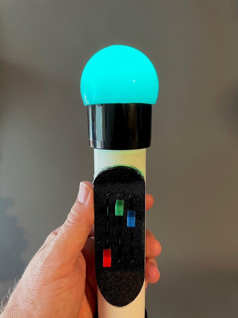
Introduction: Adjustable Multi-Color LED Orb (No Arduino Needed)


I originally wanted to make an RGB (Red, Green, Blue) adjustable-color flashlight. I wanted to stay away from Arduinos and other microcontrollers in order to simplify the build.
The circuit is simple: 3 LEDs (Red, Green and Blue in the same plastic package) each connected in series with a current limiting resistor and an adjustable resistor (aka a potentiometer) to allow the brightness of each color to be adjusted. The power source is 3 AAA batteries in series to produce 4.5 Vdc.
I found that my tri-color LED was not really bright enough for a useful flashlight and I had trouble getting the colors to mix. So I decided to make a multicolored orb. I added 3 layers (if you include the outer orb) of diffusing (mixing) the colors and the color combinations are quite pleasing.
Unfortunately digital photography sometimes has a difficult time rendering saturated LED colors. I am pretty pleased with my adjustable-color orb, although is best viewed in subdued light.
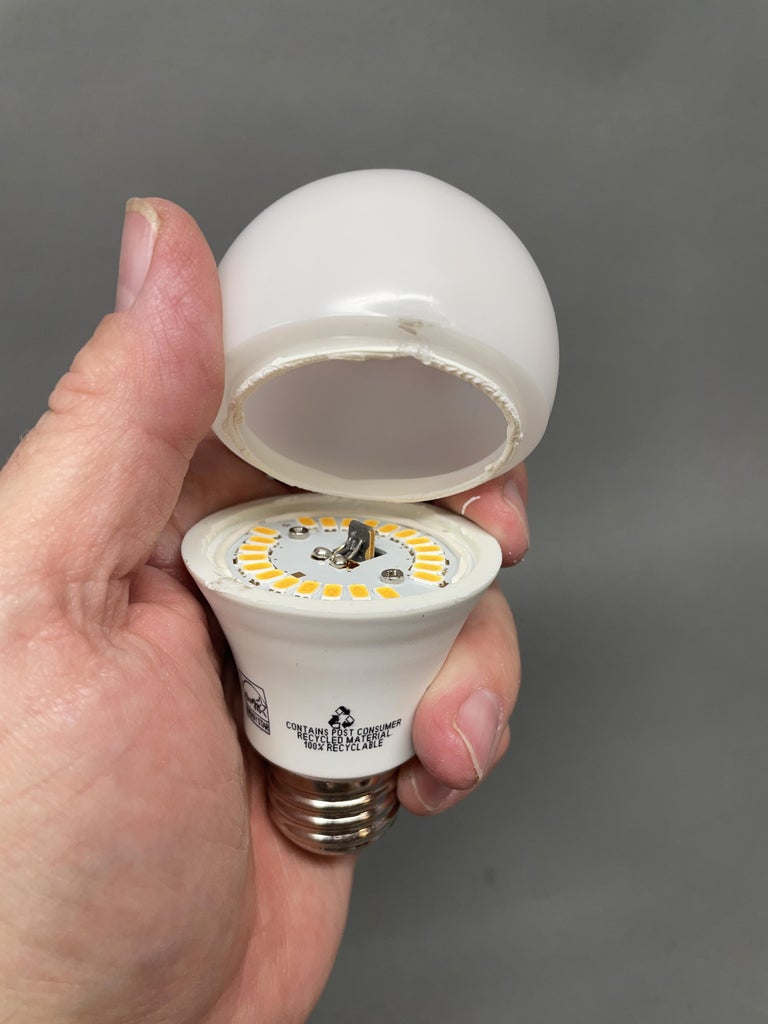
Supplies
This LED Orb uses PVC pipe for its body. However, this is not the usual Schedule 40 (SCH40) PVC pipe. It is SDR-26 PVC pipe. SDR-26 pipe has a thinner wall than regular Schedule 40 PVC pipe. I used this pipe with a thinner wall because the battery holder I used would not fit in Schedule 40 PVC pipe but would fit in SDR-26 pipe. You can use Schedule 40 PVC pipe for this project but you will have to use a different battery holder that fits inside Schedule 40 pipe.
Supplies:
- 1 - 8" length of 1-1/4" thin wall PVC pipe
- 1 - 6" x 2" x 1/16" Textured ABS sheet
- 1 - 1-1/4" Black PVC End Cap by Formufit
- 1 - 1-1/4" Black PVC Coupling by Formufit
- 1 - Plastic Globe removed from LED bulb
- 1 - 3 x AAA Battery Holder with switch
- 3 - 10K ohm linear slide potentiometers
- 1 - Common Anode RGB Superflux / Piranha 5 mm
- 1 - Plastic Prescription (or other) Bottle that fits inside PVC Pipe
- 1 - 1/16" Thick Clear Plastic
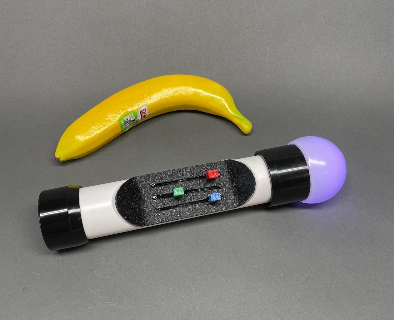
- 1 - Banana (not required)
Not Shown:
- 2 - 100 ohm 1/4 watt resistors
- 1 - 220 ohm 1/4 watt resistor
- Hook-up wire
- Self-adhesive foil tape
- Transparent tape (aka 'Scotch', the 'frosted' surface finish type)
- Miscellaneous mounting screws
- Colored construction paper
- 3D printed plastic tabs in Red, Green, Blue (optional)
- Glue suitable for the construction paper
- Sandpaper
- Hot glue gun and glue
- Soldering iron and solder
- Dremel rotary tool and 111 engraving cutter (1/32")
- Utility knife
- Heated plastic strip bender (or possibly heat gun)
- Heat Shrink Tubing
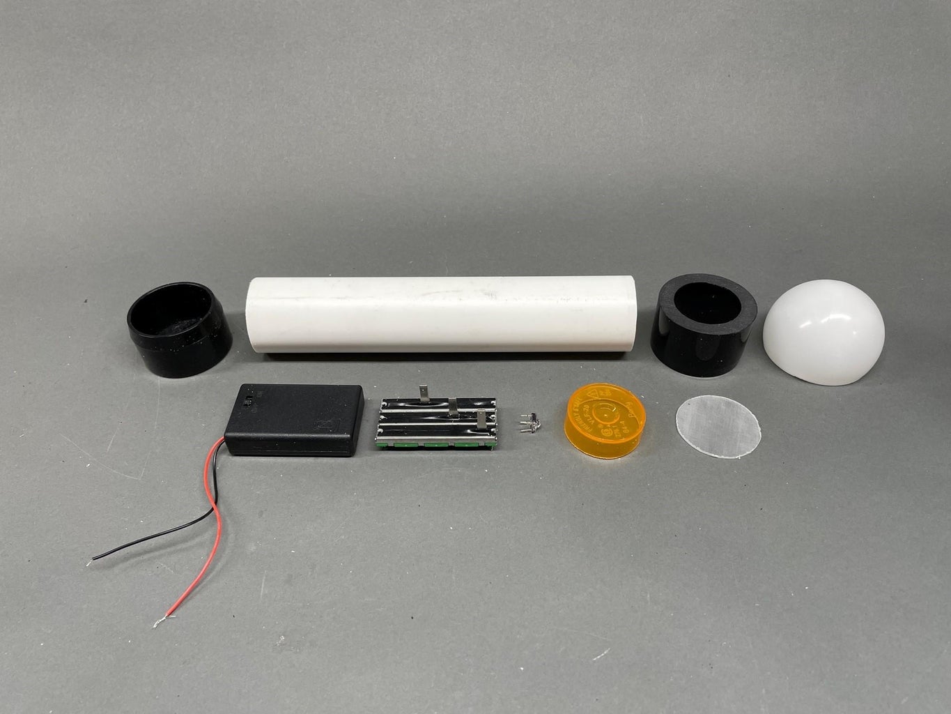
Step 1: You Need an Orb
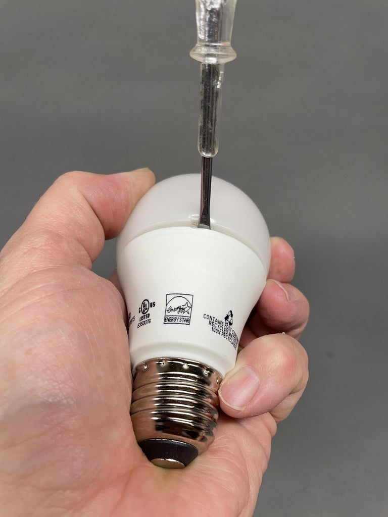
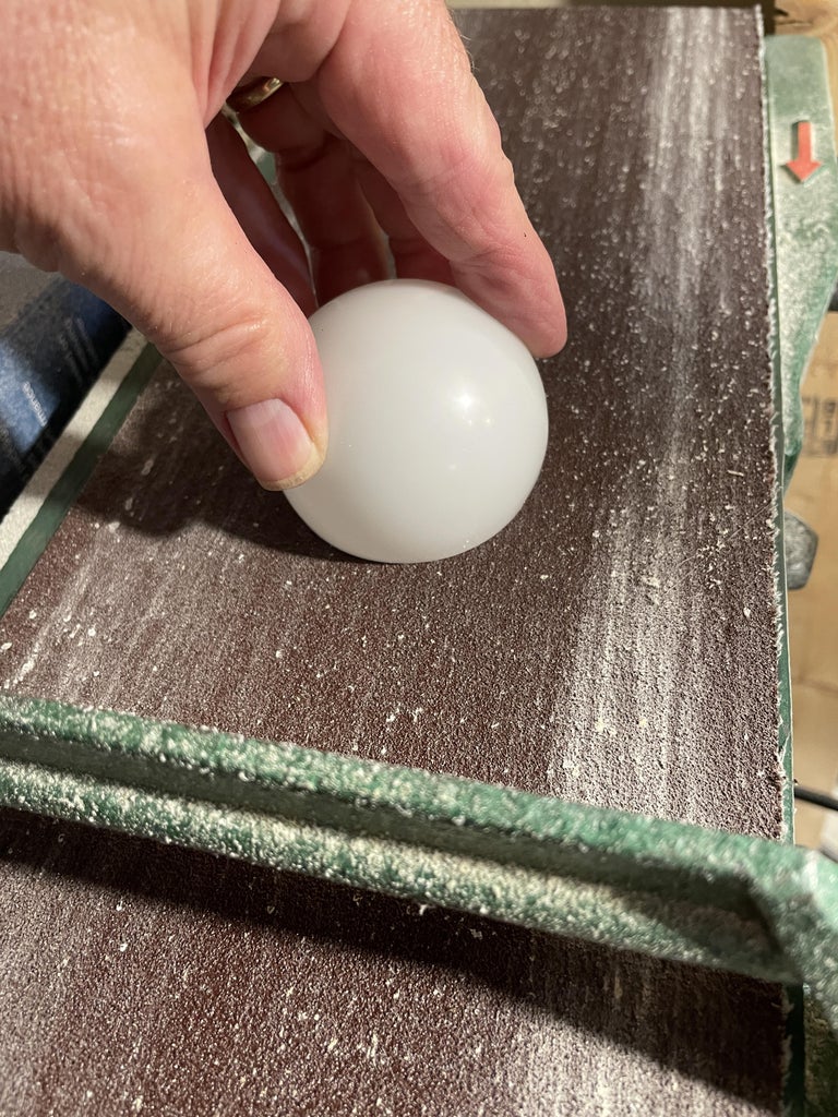
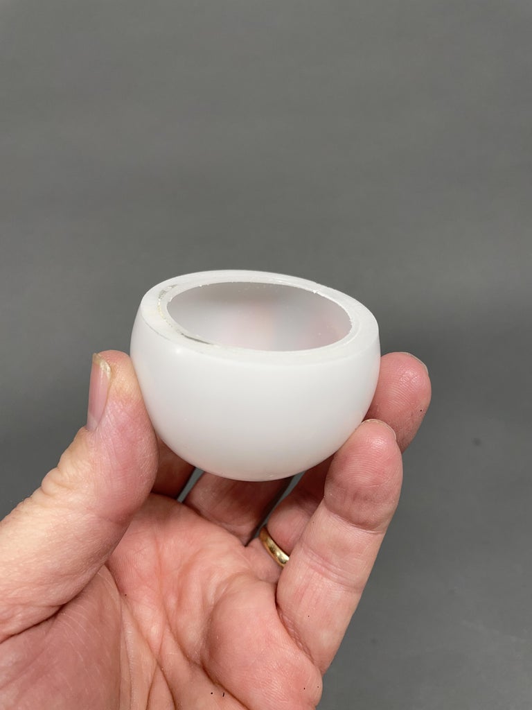
Everyone needs an orb and they are hiding all around us. Take a defective (or not) LED light bulb that has a plastic diffuser and use a screwdriver to pry it off of its base. Mine had a flange on it that I sanded off.
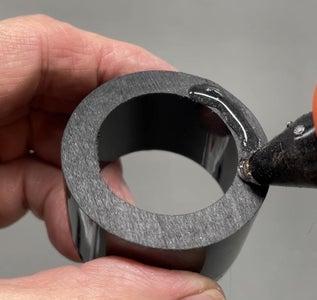
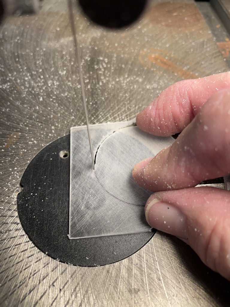
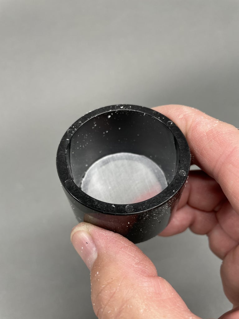
Step 2: You Also Need a Front Bezel
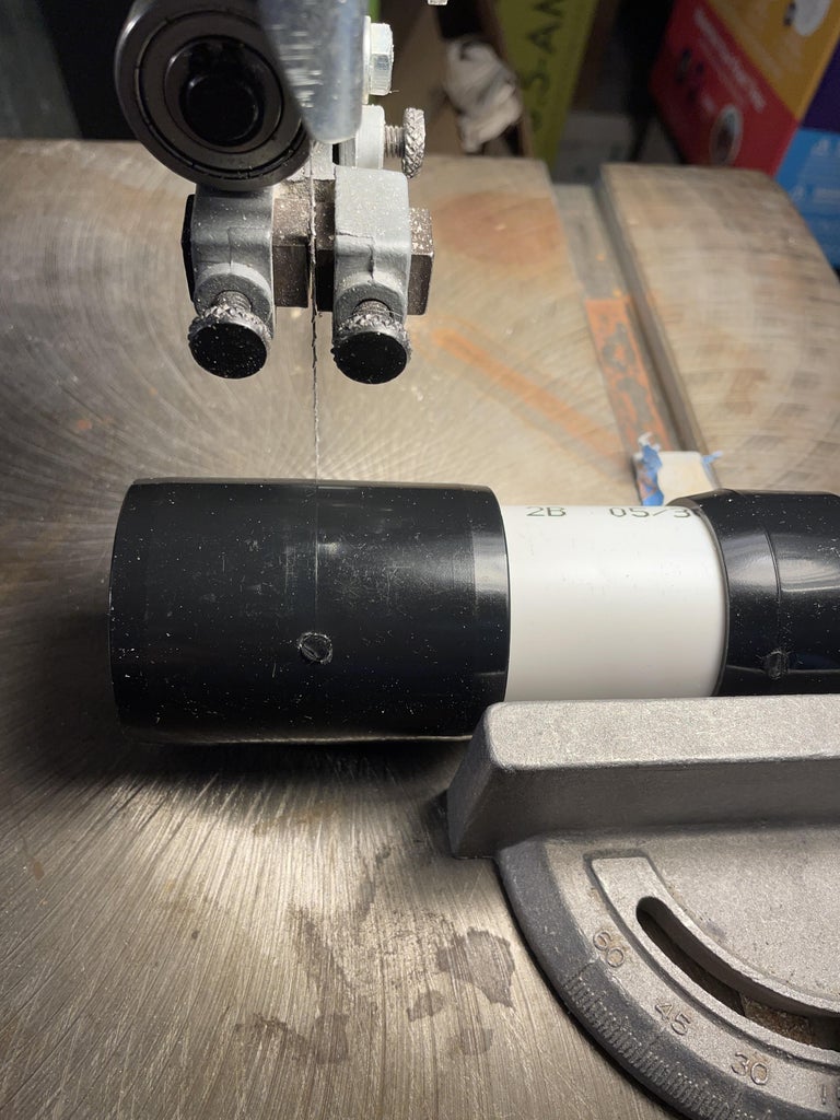
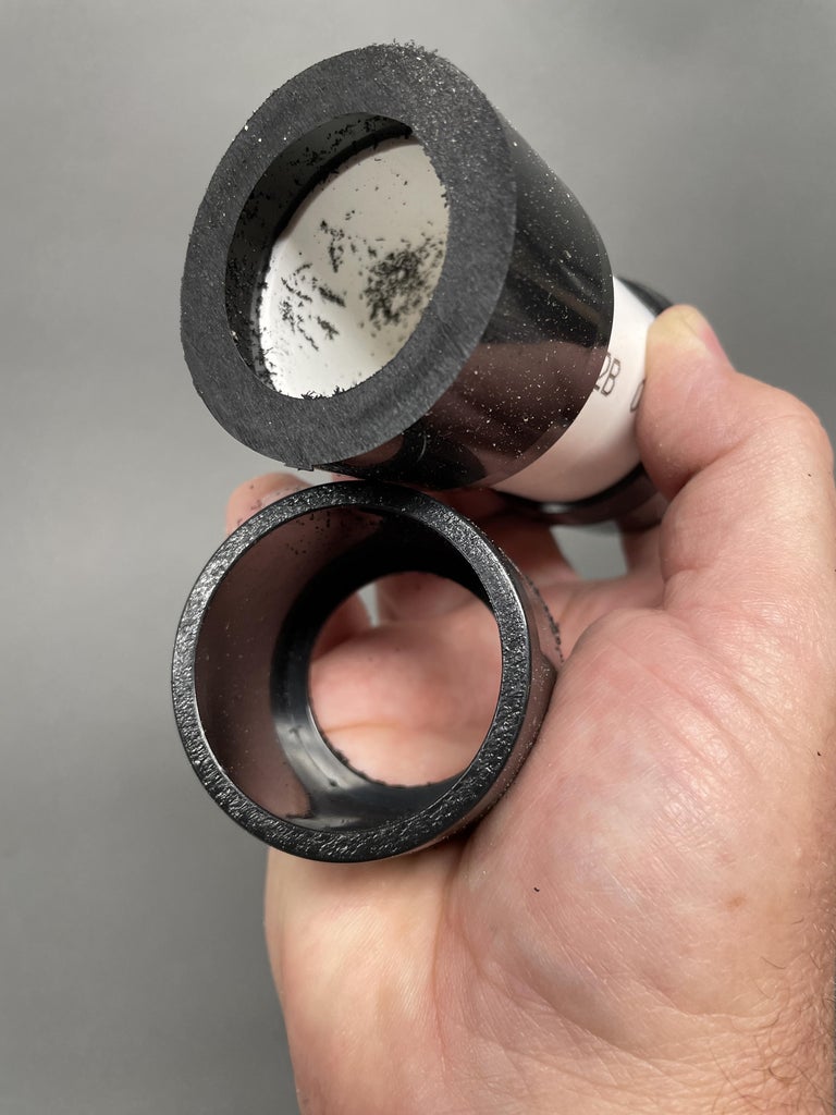
I wanted a nice looking transition from the orb to the body of the light. To do this I used a black PVC coupling by Formufit as a kind of bezel. These PVC fittings are for making furniture and look really nice. I cut the coupler down the center which ended up splitting the internal flange in two so that both halves had a nice wide flat surface to glue the orb onto.
(Save the other half of the coupler for another project.)
Step 3: Glue the Orb to the Front Bezel
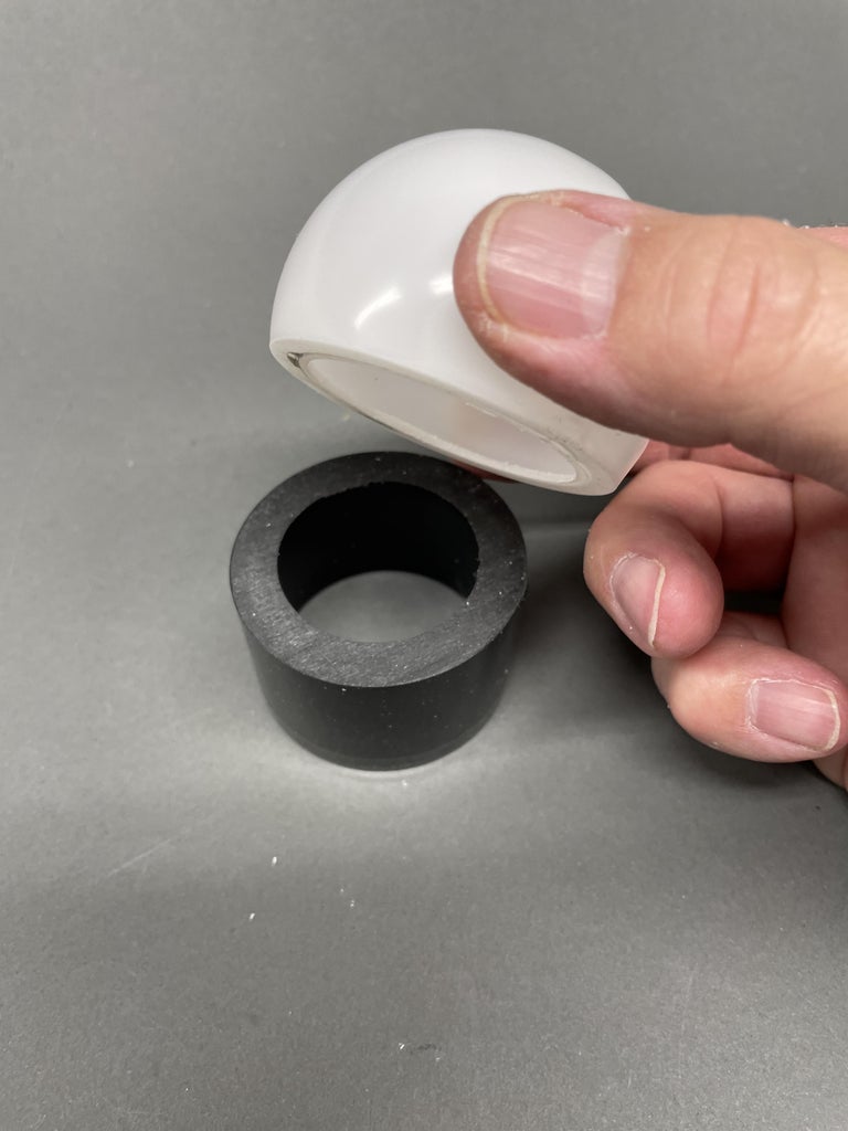
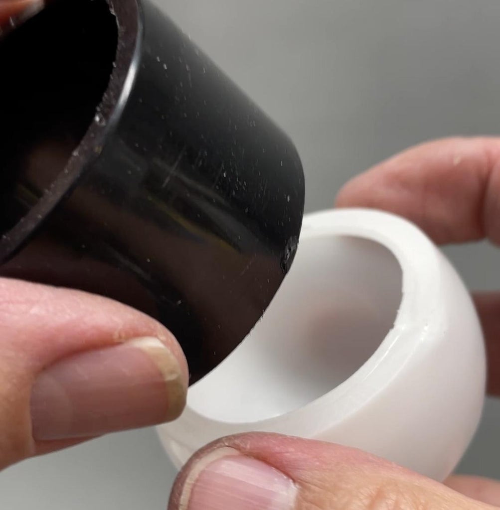
I used hot glue to attached the orb (LED diffuser) to the black PVC coupler (bezel).
Step 4: The Colors Need to Be Diffused - So Make a Diffuser
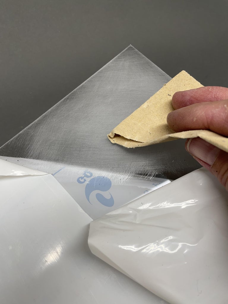
As I mentioned earlier, I initially had trouble mixing the red, green, and blue LEDs to get even colors. I decided to take clear plastic sheet and scuff it up with sandpaper. I sanded in multiple directions on both sides of the plastic. I then cut out a disk that would fit into the coupler and hot glued it in place.
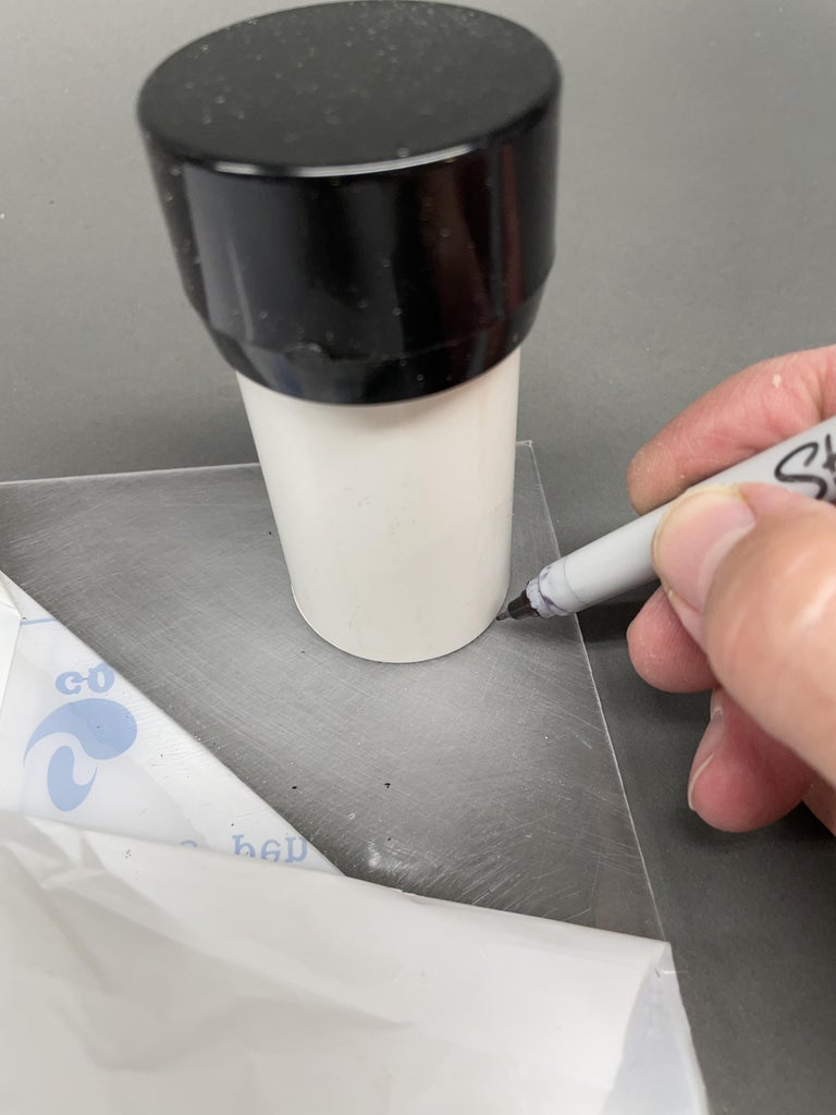
Step 5: Make an LED Holder
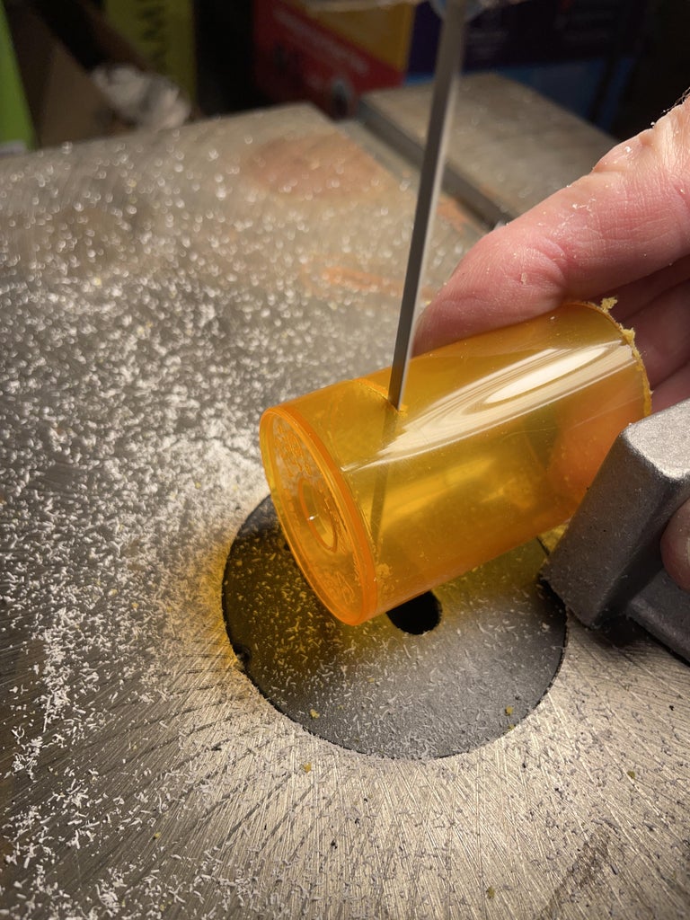

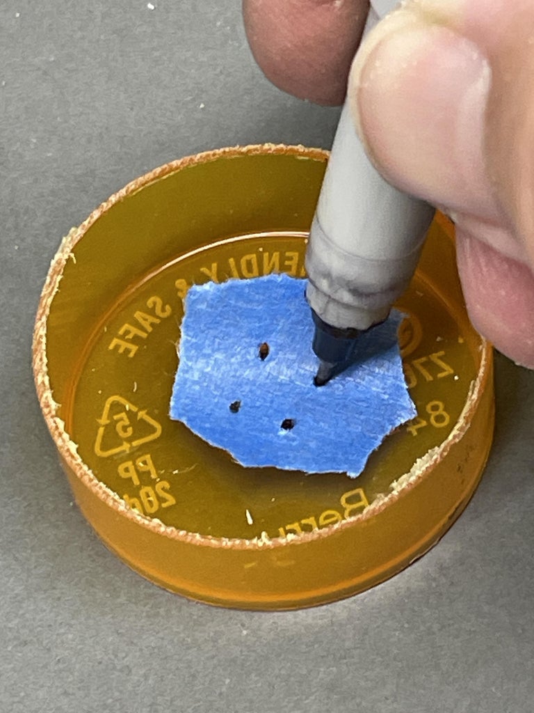
I needed some way to hold the RGB LED centered in place inside the PVC pipe. I found that an old prescription bottle fit very snugly inside the PVC pipe. I cut off the top of the bottle to make it easier to cut the bottom off square.
I made a template for marking holes for the LED's lead wires by pushing the LED's leads through some masking tape and then using the holes in the tape as a guide to mark the locations of the holes on the plastic prescription bottle. I then drilled holes in the bottle at the marks.
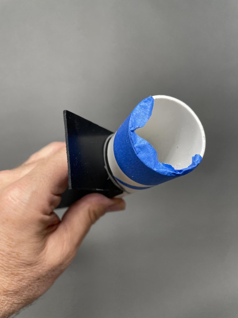
Step 6: Cut the Body From PVC Pipe
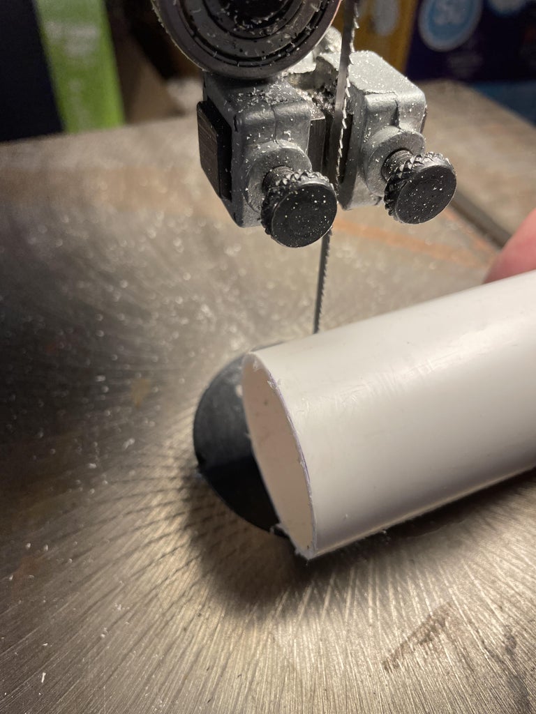
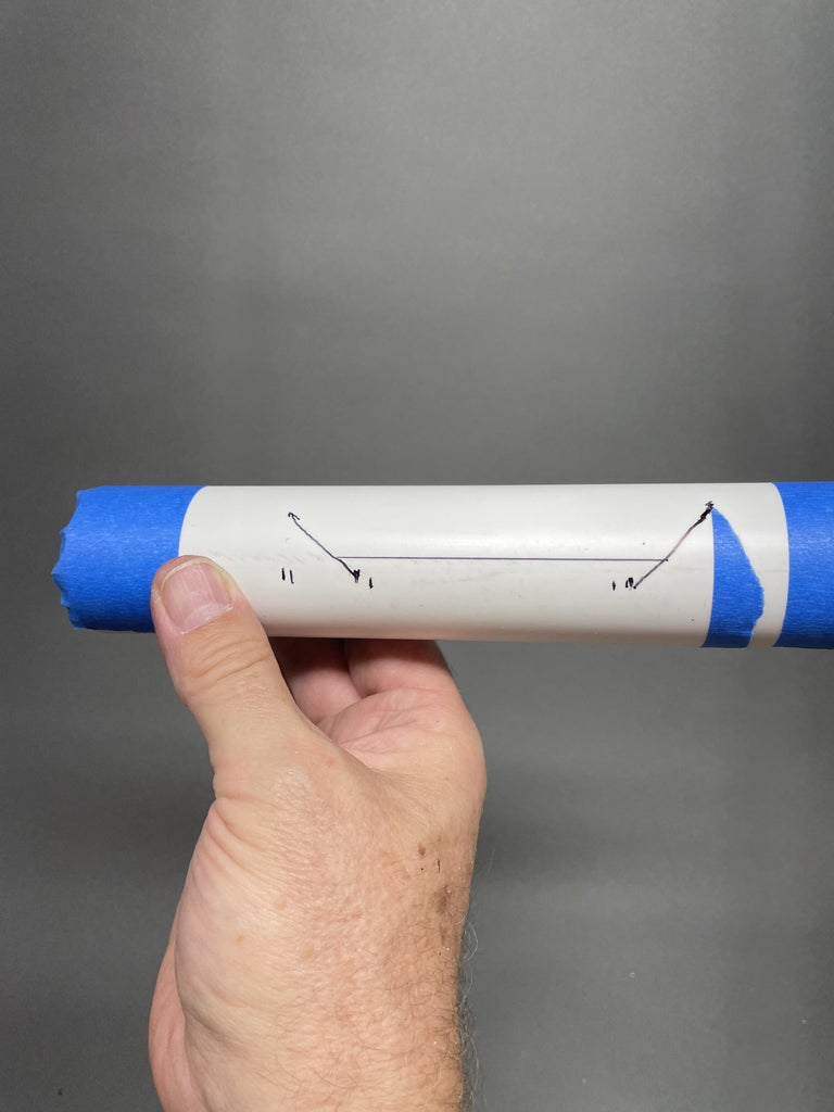
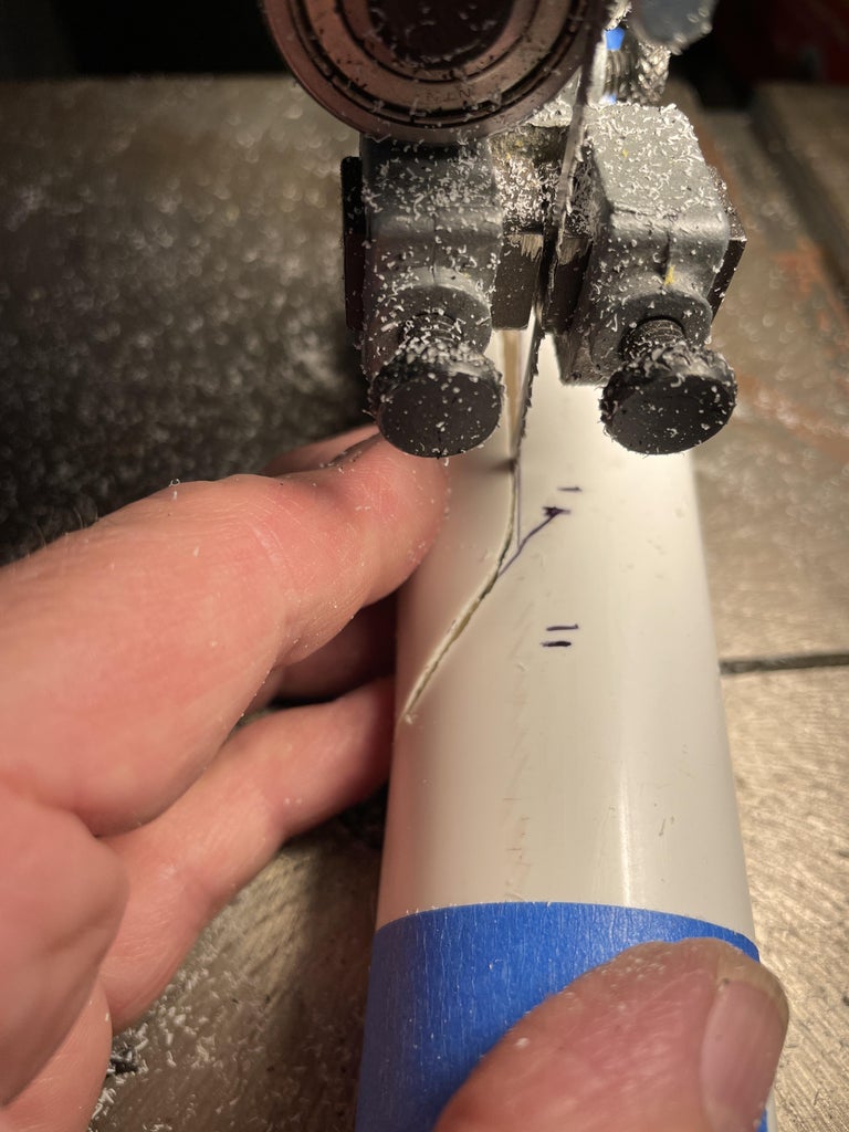
PVC pipe makes up the body of the light. I cut an 8" length of 1-1/4" thin wall PVC and lined up the battery pack, potentiometers and LED holder and sketched out how I wanted to cut out the area where I wanted to mount the potentiometers (sliders). I used a bandsaw to cut the area away I had marked out.
Step 7: Make the Slide Plate With Slots
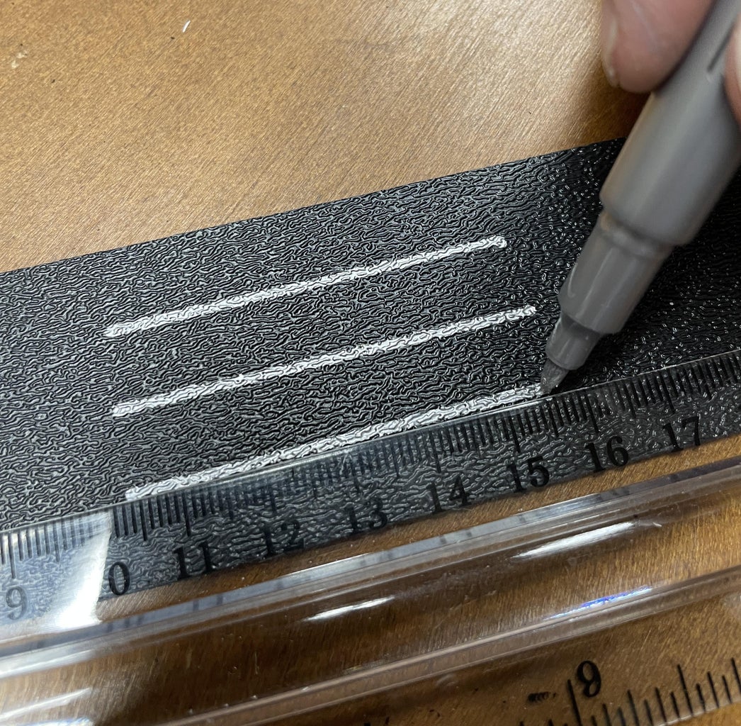
Making slots for the tabs on the potentiometers (sliders) had me trying several different methods.
I initially thought of cutting slots with my bandsaw and covering up the end where the cut entered the material with a second piece of sheet plastic. The blade kerf was not wide enough for the slider tab and the patch job was just too complicated for me.
I tried using a plastic cutting tip on a soldering gun. Again the melted slot was not wide enough and the plastic welled up on each side of the cut making it unsightly.
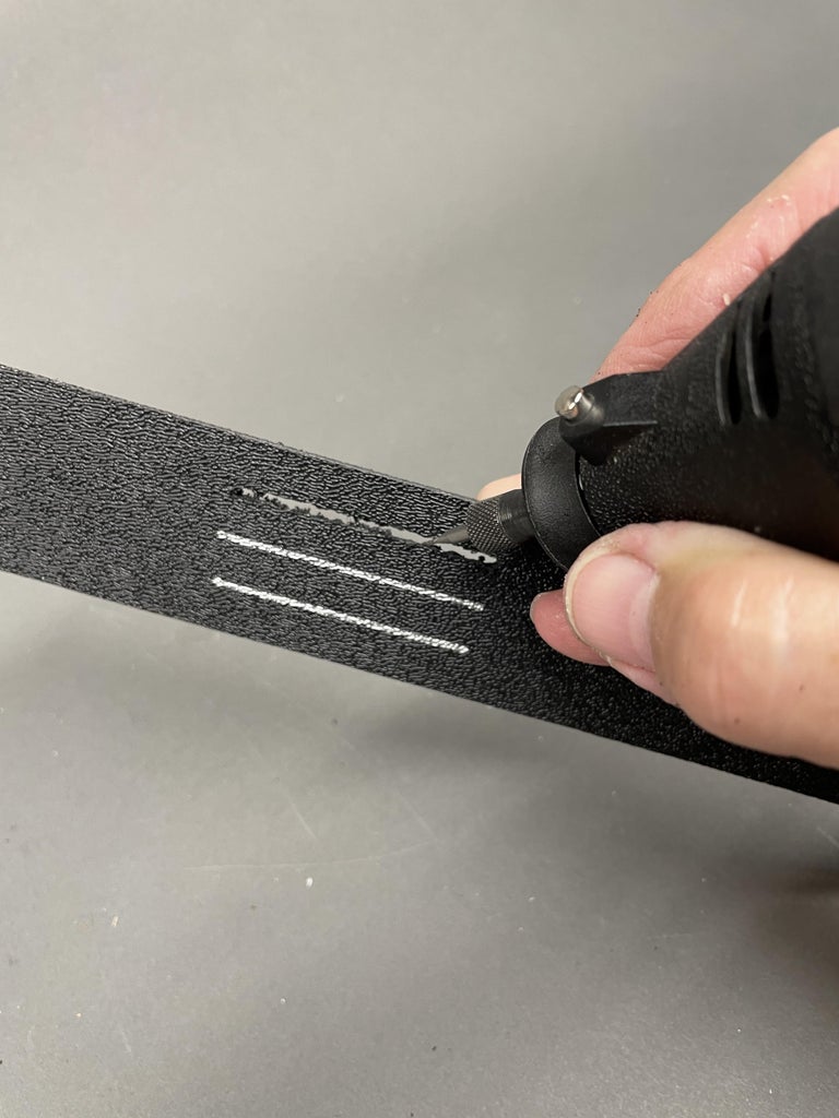
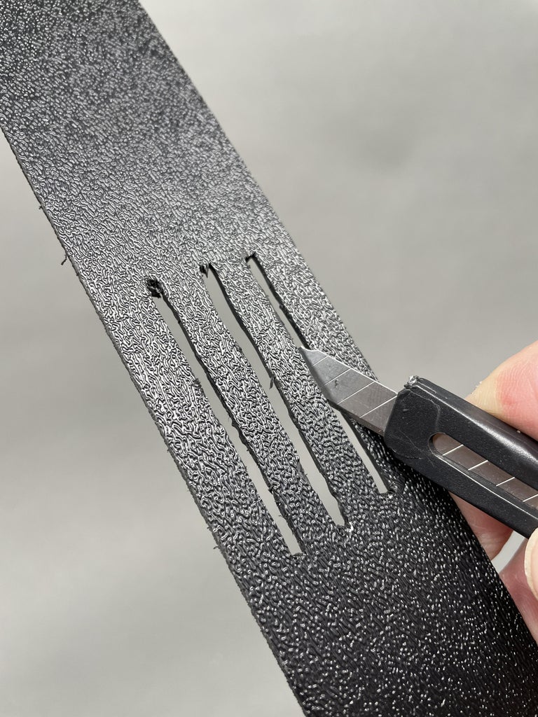
I finally settled on using a 1/32" diameter Dremel bit (#111) to cut grooves into the plastic. I cleaned up the slots with a utility knife. This worked reasonably well.
The Slide Plate was the width of the cutout in the PVC pipe so it would lay over the opening to close it off.
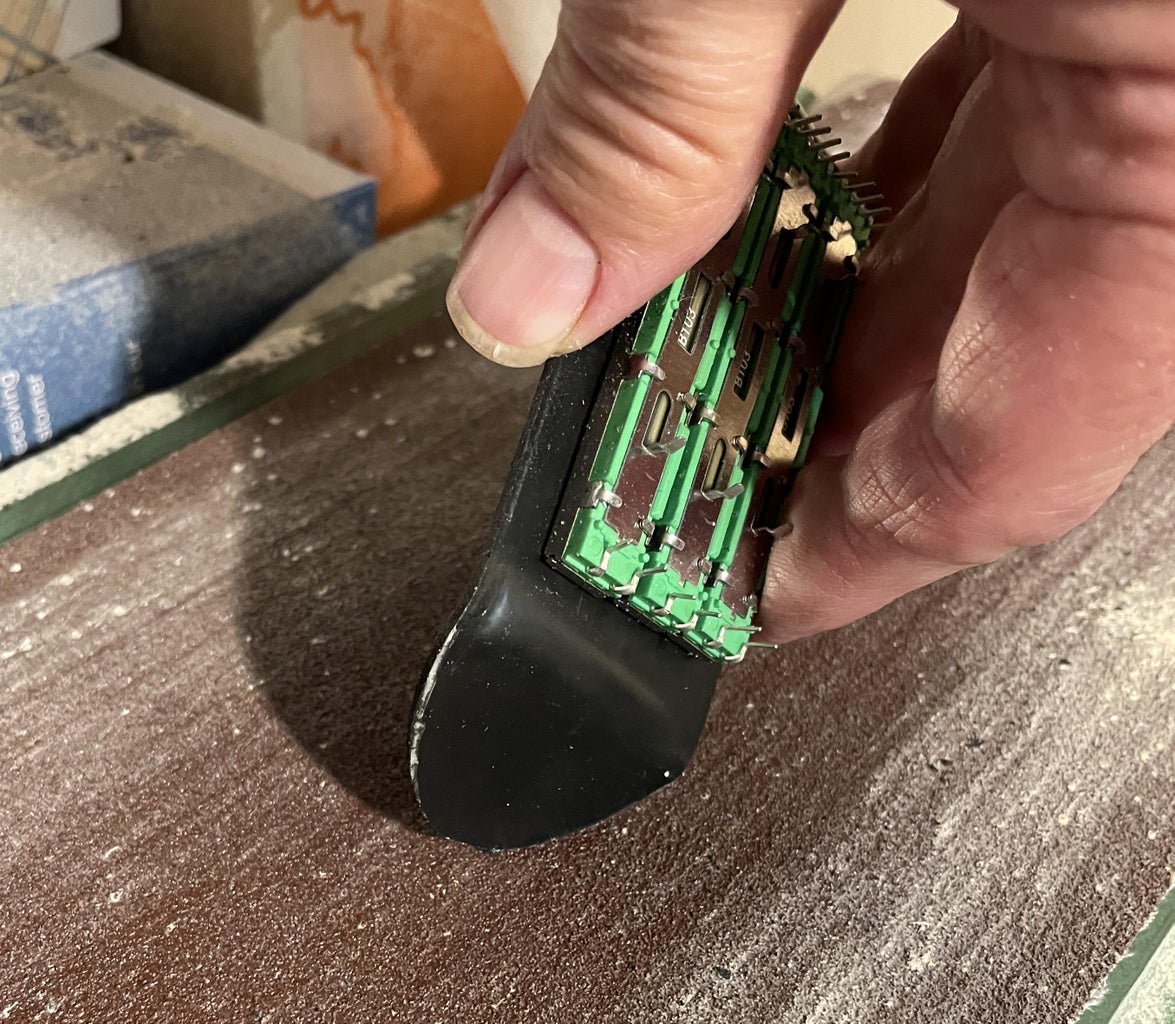
Step 8: Mount the Potentiometers to the Slide Plate
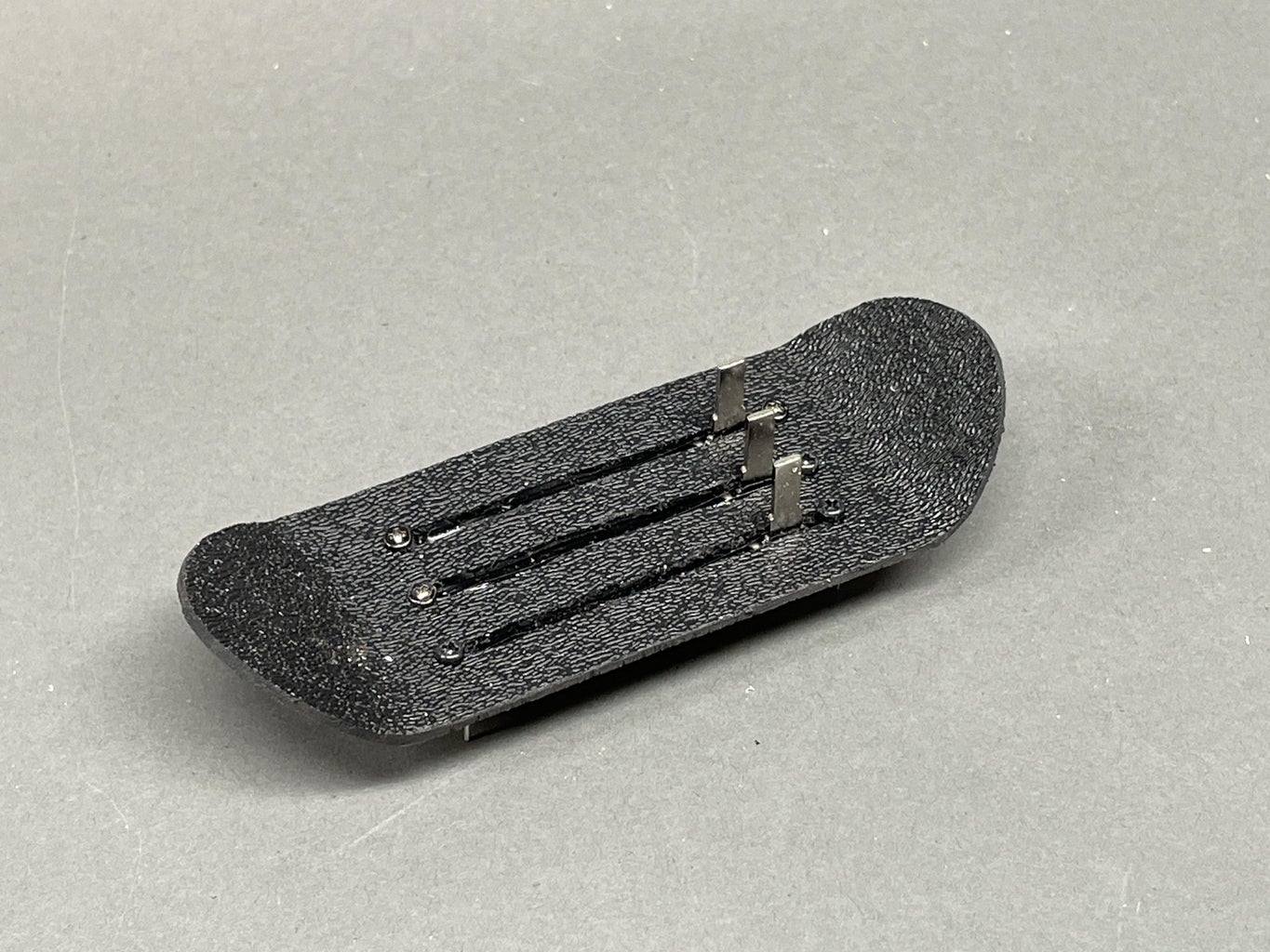
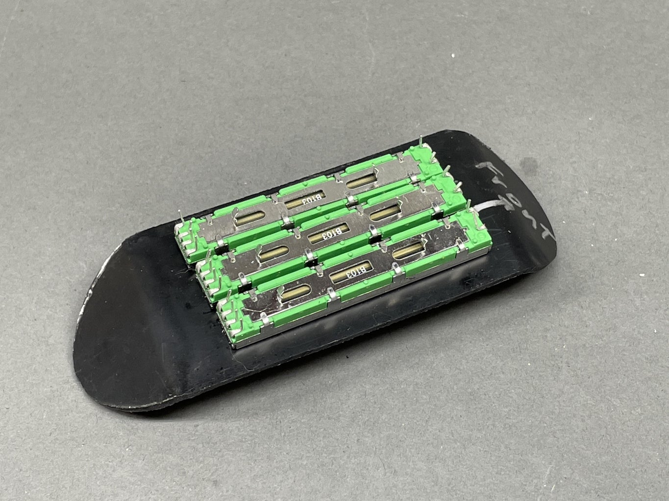
The potentiometers had a threaded mounting hole at each end. I drilled corresponding holes in the Slide Plate and used appropriate screws to mount the potentiometers. Note: The Slide Plate is shown formed (ends turned up), but it was flat when the potentiometers were mounted. Time shift trickery it is!
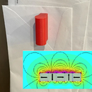
Step 9: Heat Form the Slide Plate to Fit the Cutout in the PVC Body
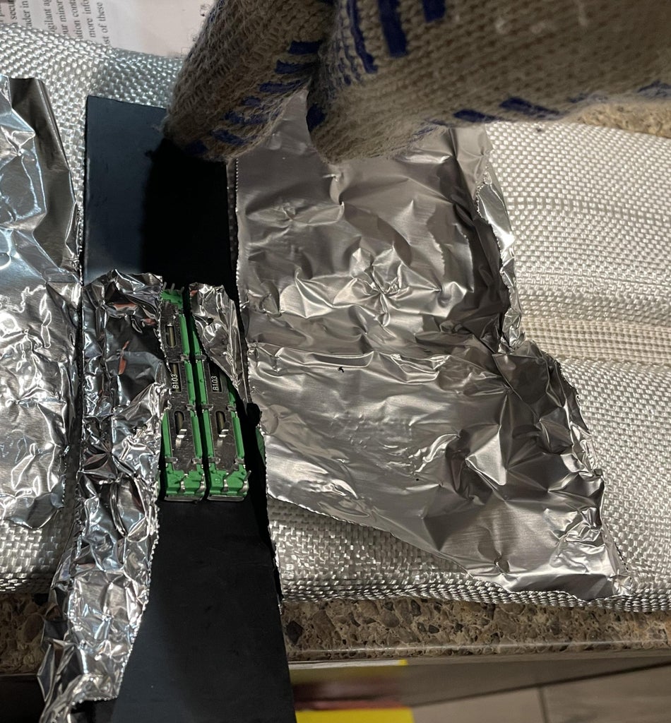
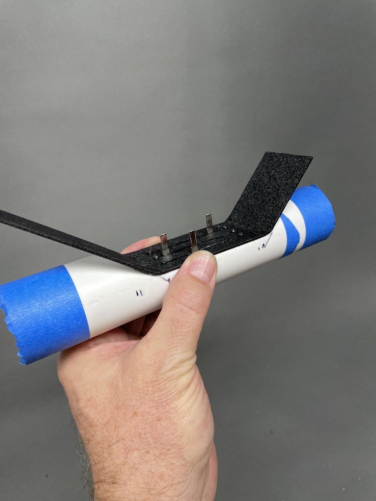
I wanted to the Slide Plate to fit neatly into the cutout I had made in the PVC pipe body. To do this I used an electric strip bender to heat up the plastic Slide Plate until it was flexible and bent it to the angle needed to fit down into the cutout.
The strip bender is nice since it heats in a narrow strip (go figure) of area so that the other areas of your plastic stay rigid. I typically put aluminum foil over the part of the plastic I want to shield from the heat. I also put foil on either side of the plastic I'm heating in order to concentrate the heat under the plastic and make it soften faster.
A strip bender is a pretty specialized tool. It is a tape heater (heating wire woven in glass fiber ribbon) mounted in a wood groove lined with aluminum foil and fiberglass cloth. The plastic you want to soften lays across the grove with the heater under the plastic.
As an alternate method to a strip bender it might be possible to heat up a narrow strip of the Slide Plate by shielding the parts you want to stay rigid with wood or cardboard and using a heat gun. I would practice on scrap plastic before committing my piece with the slots cut into it. ;-)
Step 10: Sand the Slide Plate to Fit
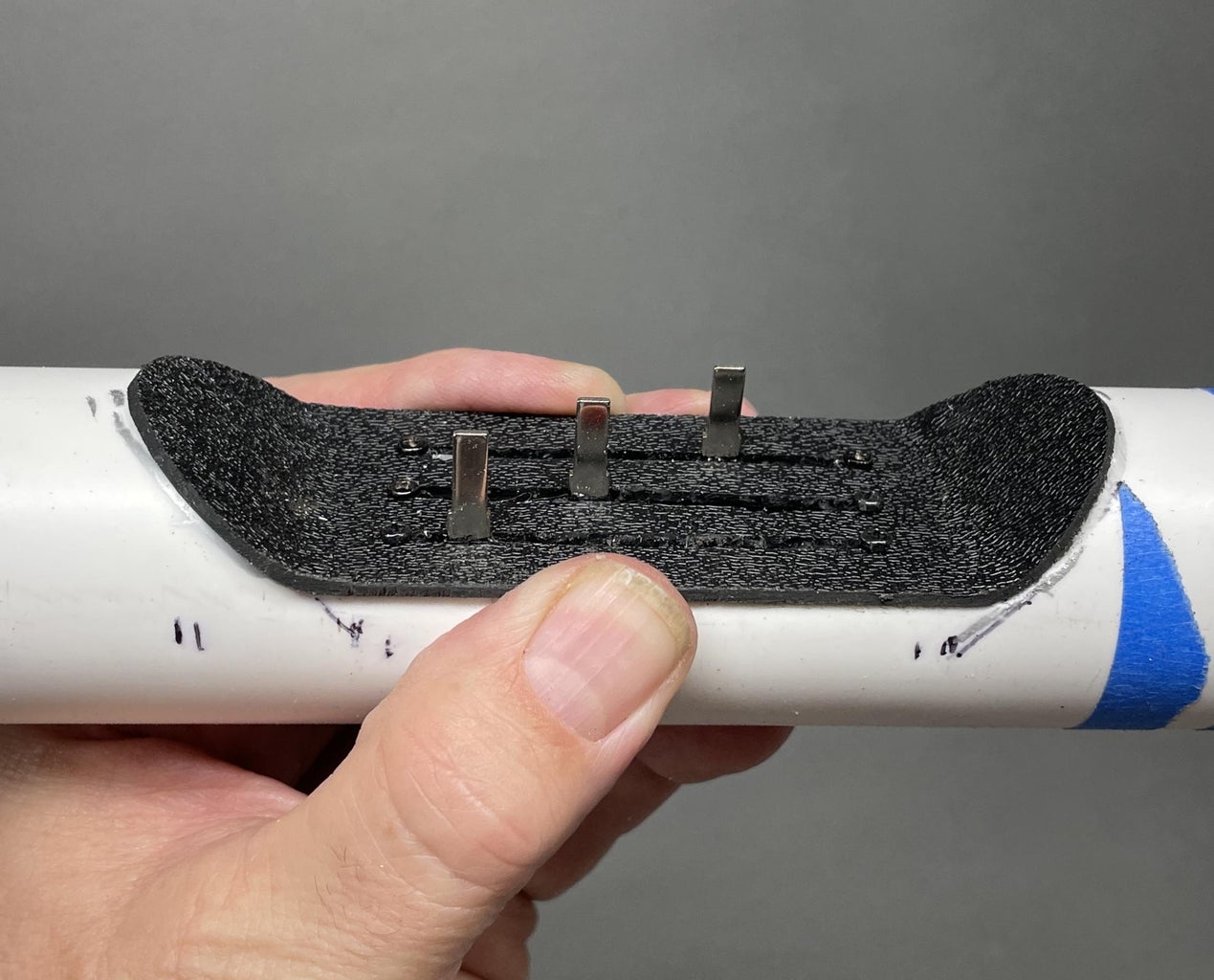
I placed the Slide Plate into the PVC pipe cutout and marked the curves indicating the material I needed to remove in order to match the cutout in the pipe. I tired to saw these curved outlines but ended up using a sanding belt to shape the plastic to the correct contour.
Step 11: Wire the LEDs, Add 2nd Diffuser, Mount
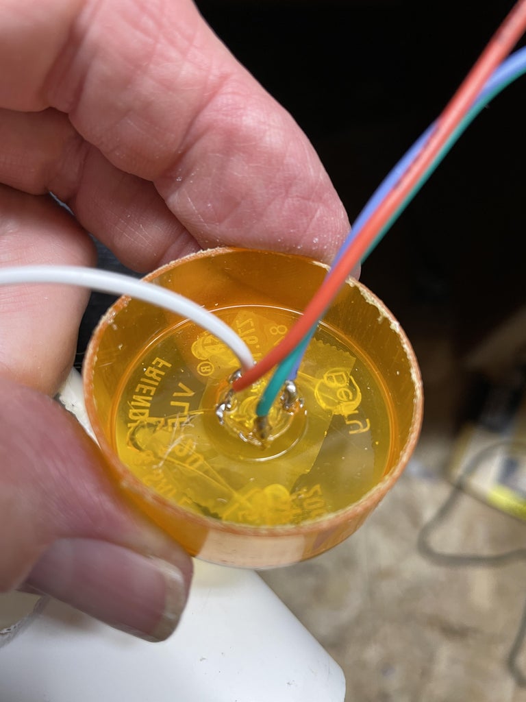
I put a dab of hot glue under the LED package and pushed it into place with the LED's lead wires (pins) going through the holes I had drilled earlier in the prescription bottle. I soldered a white wire to the Common Anode and Red, Green, and Blue wires to the corresponding cathode pins of the LED.
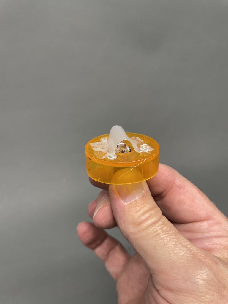
I wanted as much diffusion as possible so I placed a loop of transparent (aka 'Scotch', the 'frosted' surface finish type) tape over the LED and tacked it into place with 4 daps of hot glue, in case the adhesive on the tape decided to give up in the future. I pushed the prescription bottle into place in the pipe near the front, inserting it through the cutout. I applied aluminum foil tape inside the pipe to reduce light leaks from shining out through the sides of the thin wall PVC pipe.
Step 12: Wire LEDs to Potentiometers and Mount Slider Plate
Connect resistors. The Red LED wire has a 220 ohm resistor connected in series with it. The Green and Blue LEDs each have a 100 ohm resistor connected in series with each of their corresponding wires. The soldered wire splice and resistors were covered with head shrink tubing. The free lead wires of the resistors were wrapped around the corresponding pin of the potentiometer and soldered in place.
After a test fit I used hot glue to mount the Slider Plate to the PVC pipe.
Step 13: Connect Battery Pack
The ends of the potentiometers near the battery holder were all connected to the negative (black) battery holder lead wire. The red lead wire of the battery holder was connected to the white wire connected to the common anode of the LED.
The battery holder fits nicely inside the PVC pipe and the black PVC end cap is just held in place by friction (as is the front bezel also) so that it can be removed to get to the battery holder switch to turn the light on and off.
Step 14: Make Red, Green, and Blue Tabs for Sliders
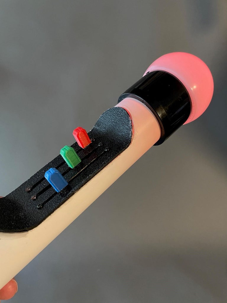
Originally I took the simplistic approach and made sleeves out of colored construction paper for the slider tabs and glued them in place.
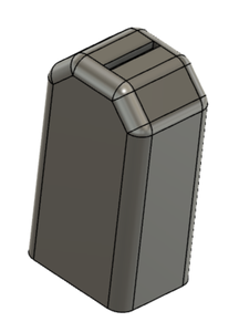
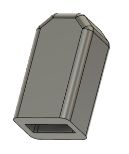
They I decided to 3D print Red, Green and Blue plastic 'knobs' for the slider tabs. If you have access to a 3D printer you can design (I used Fusion 360) and print colored 'knobs'. I have attached the .stl file for reference.
Attachments

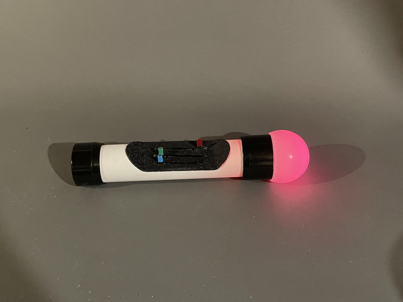
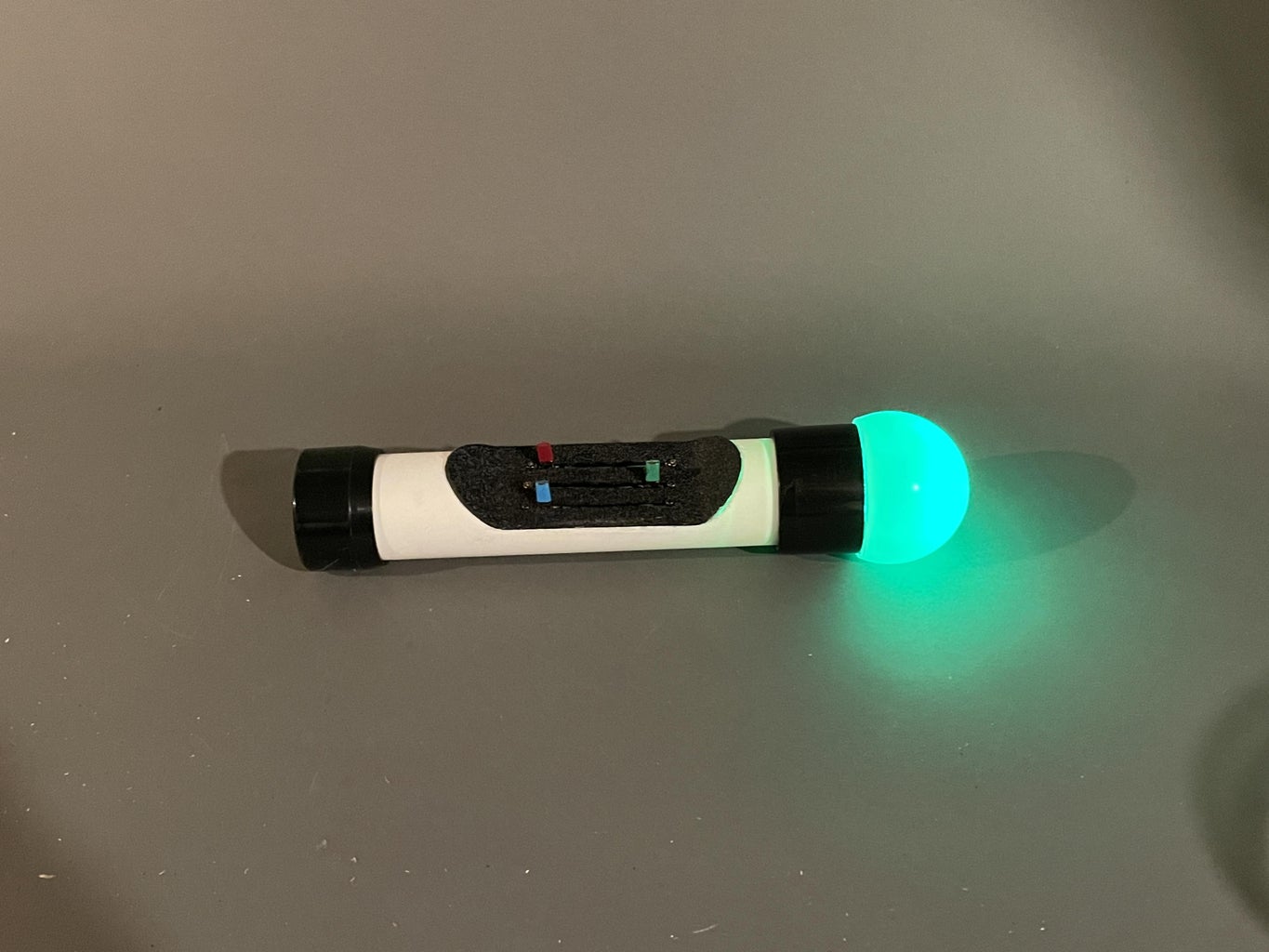
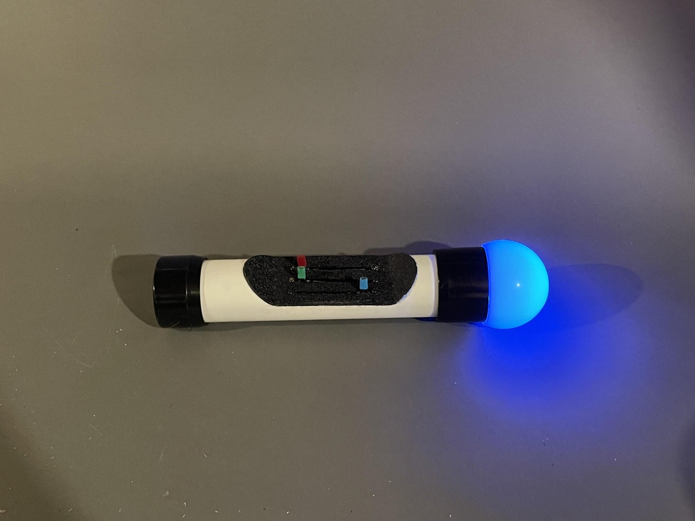
Step 15: Enjoy 'orbing'
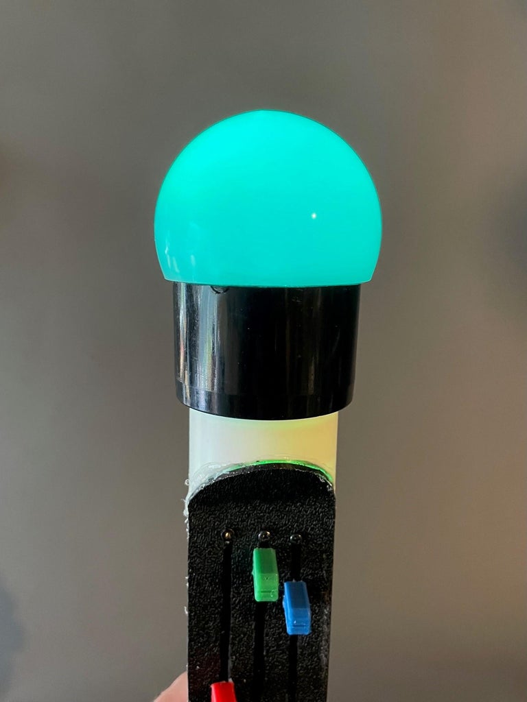
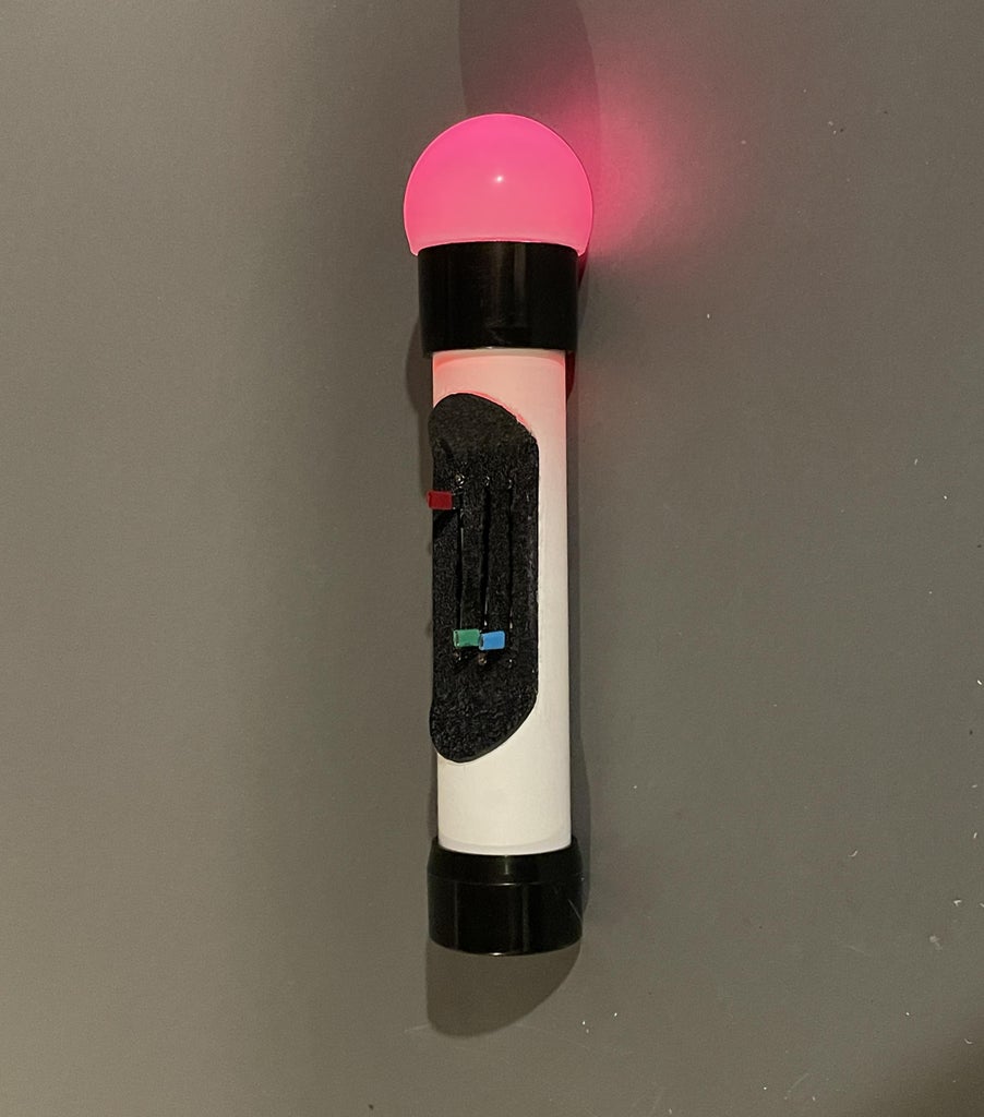
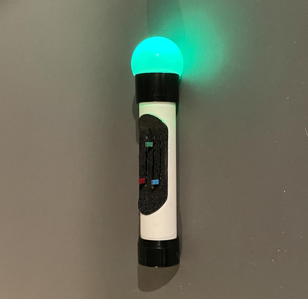
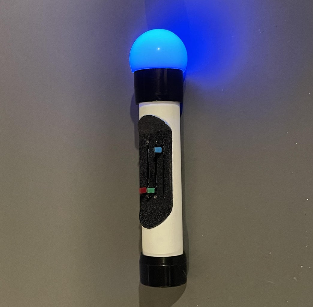
Dial in any one of the millions of custom colors available and go 'orb' someone.
Enjoy!

Finalist in the
Colors of the Rainbow Contest


Comments