
Introduction: Rotating LED Display
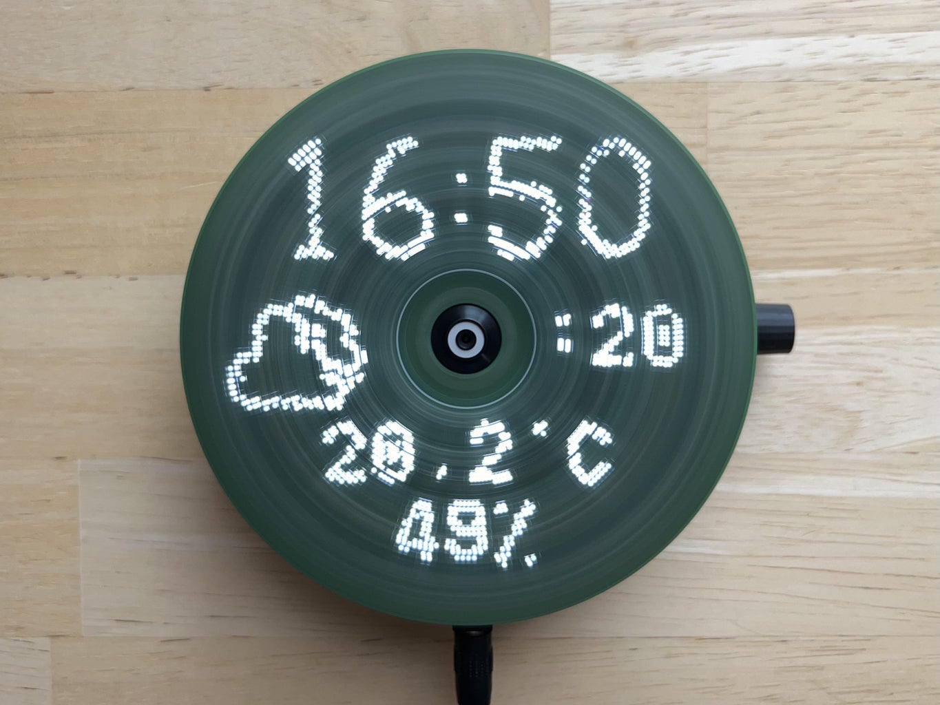

The Rotating Display is a compact disc-sized device that rotates quietly using a CD motor. It features 40 LEDs that display time and weather data sourced from the internet. The device is wirelessly powered and controlled via a user-friendly web interface. It uses Arduino nano and ESP-01s microcontrollers and is easy to assemble.
Supplies
Attachments

Step 1: The Story
The Rotating Display is a compact disc-sized device that rotates quietly using a CD motor. It features 40 LEDs that display time and weather data sourced from the internet. The device is wirelessly powered and controlled via a user-friendly web interface. It uses Arduino nano and ESP-01s microcontrollers and is easy to assemble.
The highlights of the display include:
- a simple design with few mechanical components
- easily replicable wireless power supply with printed coils
- alternating arrangement of the LEDs to achieve higher resolution
- complete balancing of the display board to ensure vibration-free operation
- timer controlled clocking of the LEDs and regulation of their brightness
- user-friendly user interface via a standard web browser
- retrieval of time and weather data from the internet
- implementation of a file browser for the ESP-01’s flash disk for uploading image data
- transparent, object-oriented structure of the ESP-01s software
Step 2: How to Use the Display
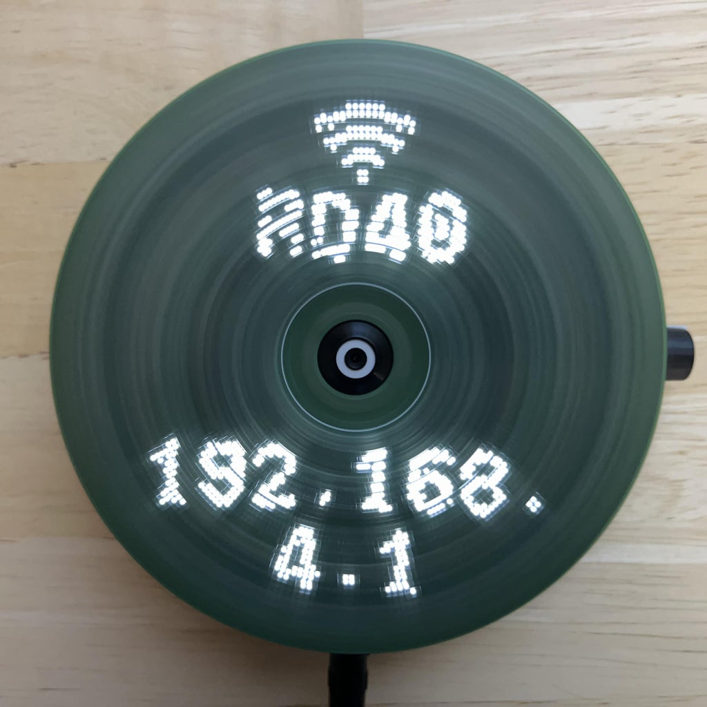
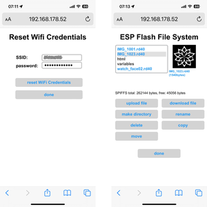
When switched on, the device tries to connect to a known wifi. If no valid wifi credentials are found, the unit will be configured as wifi access point. In this mode, a computer or mobile device can be connected, directly (SSID: RD40, no password).
Once the wifi connection has been established, the unit will display its IP address on the home page of the device. Enter this address in your web browser. This will load the web user interface and will allow you to configure your local wifi.
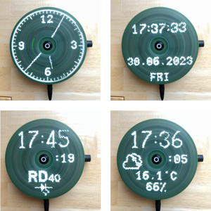
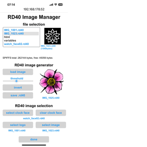
There are several operating modes that display time and weather information. The logo clock mode integrates a customizable image into the clock face. The image can be easily uploaded from the user interface. The same is true for the analog clock, which uses a customizable clock face in the background.
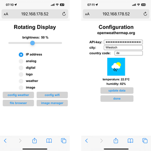
Device operation is managed through a web interface, accessible from any web browser. The interface allows users to manage login credentials, upload image files to the display, and control image and configuration files through a file manager.
Step 3: The Structure of the Device
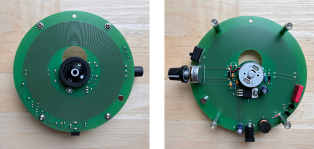
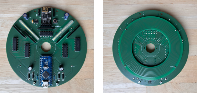
The device consists of two sub-assemblies: power supply and display. The power supply board is also the base plate, which can either be placed on a flat surface or hung on a wall. A standard CD motor is inserted through a recess in this board so that the CD tray above the board can accommodate the display assembly. The display board is fixed with two M2 screws. Furthermore, the base plate carries a potentiometer to control the motor speed as well as an on/off switch for the motor.
The core of the power supply board is a circuit for wireless power transmission to the display. It uses very few components, but a quite complex transformer coil. In order to make the device easy to re-build, the coil isimplemented as a printed circuit.
A CD motor in the middle of the power supply board rotates the display. Next to the motor, there is a variable voltage regulator, which controls the rotation speed of the motor.
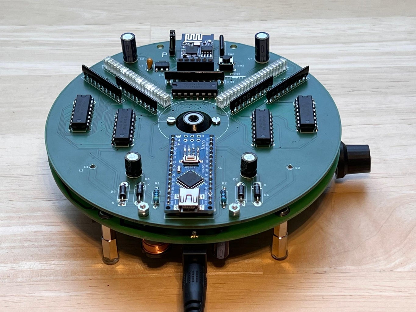
The main components of the display board are two LED rows with 20 LEDs each, five serial shift register chips, and two microcontrollers (Arduino nano and ESP-01s). On the backside of the board the secondary coil of the wireless power supply is attached.
A Hall sensor synchronizes the rotation of the disk with the control of the LEDs. The LED output is done via the SPI interface of the Arduino nano and the shift registers.
The ESP-01s generates the image data shown on the display and sends it to the Arduino via an I2C interface. It obtains time and weather data from the Internet, to which it is connected via a Wifi interface. Using the same connection, the user can access a web server that runs on the microcontroller and hosts the display's user interface.
Step 4: How to Assemble the Rotating LED Display

4.1. component supply
The parts list and all necessary documentation is available on github. The Bill of Material also contains sources and corresponding links for purchasing the parts.
4.1. electronic components of the power supply
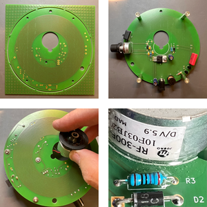
Start with assembling the power supply board. Insert and solder all electronic components. The PCB documentation is available on Github. Afterwards, insert the CD motor from the soldering side and bond it with a fast curing two component epoxy resin on the component side of the PCB.
4.2. CD tray PCB
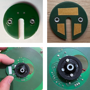
Glue two M2 nuts into the CD tray PCB. Attach it with double-sided adhesive tape to the back side of the CD motor tray. Two M2 screws may help to bring the PCB into the right position.
4.3. Rubber bumpers and magnet
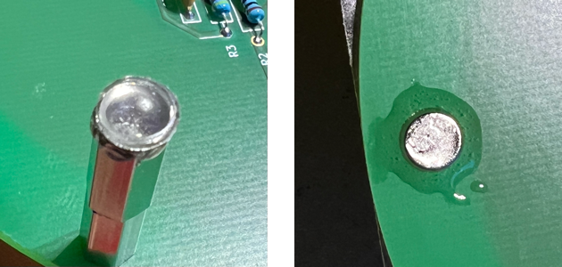
Rubber bumpers are glued with the epoxy resin to the ends of four 20 mm long bolts. The bolts serve as feet of the power supply. The magnet is glued into the hole provided at the edge of the power supply disc. Attention: the correct orientation of the magnet (with the right side up) is very important! Make sure that the device works properly before you glue the magnet!
4.4. assembly of the display PCB. The LEDs.
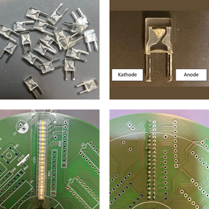
Continue with the display board assembly. First prepare the LEDs by shortening the wires. Insert them one row at a time. Hold the LEDs in place with tape before soldering. Note: The LEDs must be inserted in the correct orientation. Use the picture as a reference to identify the cathode and anode of the components. Note the marking on the PCB (A = Anode, K = Cathode).
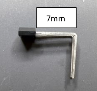
4.5. install the Hall sensor
Prepare the Hall sensor as shown in the picture. Note: The Hall sensor is the only component, that is inserted through the holes from the soldering side! It needs to be installed before you insert the Arduino nano, as the Hall sensor is soldered on the component side of the PCB.
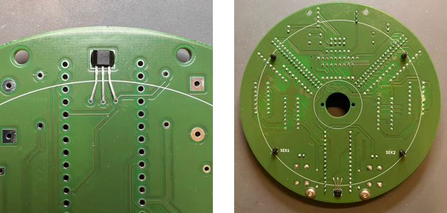
4.6. insert and solder the rest of the components
Insert and solder the remaining components according to the PCB documentation on Github. Finally, the secondary coil PCB can be attached using 4 pins.
Step 5: Uploading the Software and Necessary Data to the Microcontrollers
Install Microsoft Visual Studio Code on your computer. Load the platformIO extension. Familiarize yourself with the system. There are numerous tutorials on Visual Studio Code and platformIO on youTube.
Download a copy of the github repository and store it on your computer, locally. Open the folder “RD40_Arduino_nano” in Visual Studio Code. Connect the Arduino nano to your computer using a mini-USB cable. Make sure, the cable provides not only the power lines, but also data (not all mini-USB cables do so!). Start the compilation and the data transfer with the P button of the platformIO extension. The program will notify, when the process is completed.
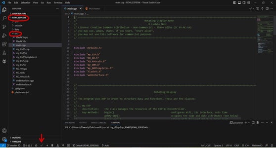
Next, close the “RD40_Arduino_nano” folder in Visual Studio Code and open the folder “RD40_ESP8266”. Connect a FT232 level converter to your mini-USB cable. The little adapter is available from many sources – search for “FT232”. Plug the FT232 into the female 6-pin connector on the display board. Make sure, the orientation is right. For reference, there is a little picture next to the connector, which shows the correct orientation. Set the jumper on the display board to position “P”. Power on the display by connecting a 12V/2A power supply to the power jack of the power supply board. Push the reset button on the display board next to the female connector of the FT232 in order to start the programming mode of the ESP8266. Now, you can start the compiler and data transfer by clicking on the P button of the platformIO extension.
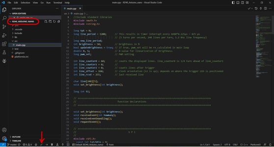
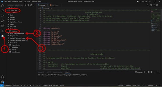
Once done, leave the FT232 adapter and USB cable in place. As a last step, we need to transfer the data to the flash drive of the microcontroller. Before you can transfer data to the microcontroller, you need to push the reset button again (jumper in position “P”). Now, the microcontroller is in programming mode. Go back to your computer. The data of the disk is also in the “RD40_ESP8266” folder (you can find it in the data sub-folder). So, leave “RD40_ESP8266” open, click on the platformIO icon (see picture, click #1). Then, click on “Build Filesystem Image” (click #2) to generate the image for the flash disk. Finally, upload the image to the microcontroller with the “Upload Filesystem Image” button (click #3).
Step 6: Setup the Rotating LED Display
Once the software and data is uploaded to the microcontrollers, set the jumper back to the running position (without label). Restart the display by pulling the power plug and reconnecting again. Switch on the motor. Now, the system should run properly and display the home screen with the wifi information. Use your computer to connect to the wifi (SSID RD40, no password) and start a web browser. Enter the displayed IP address in the address line of the browser. The user interface page will be loaded. You can edit the wifi credentials by clicking on the “config wifi” button if the user interface. Enter the data for your local wifi, click on “done”. Re-start the display. Now, the device will connect with your local wifi and will display it’s new IP address.
If you would like to use the weather clock mode, you need to configure the access information to openweathermap.org. In order to do so, you need to register and subscribe to the “Current Weather Data” Service, which is free of charge. The platform will provide an API-key, which you need to copy to the UI of the Rotating Display.
Uploading images, converting them to black & white, and downscaling the resolution to 110x110 pixels can be done with the “image manager” page of the user interface. Make sure your image has a square shape. The software can deal with a wide range of image formats and resolution. As a last step, select an .RD40 image in the selection box by long clicking on the entry. Assign the image to the analog clock, the logo clock, or the image mode by clicking on the respective button.


14 Comments
5 days ago
This is soooo fascinating! The amount of research and trial-and-error that you put into this must be immeasurable. The manner in which you use the shift registers is intriguing.
Have you considered using color LEDs?
Reply 3 days ago
yes, indeed. I have thought about a color display.
However, this would be a real stretch. First and foremost, the memory size of both the Arduino nano and the ESP8266 would not be sufficient for a color image. Here is the simple calculation: The current display needs 40 bit per line (5 bytes), the number of lines per round is 240. This makes 1200 bytes for one image. The nano has 2048 bytes of SRAM, only.
If we want to make a real color display, we would need to deal with brightness levels (on and off would not be sufficient). If we assume we use 8 brightness levels per color, we would need 3 bits * 3 colors * 40 pixels/line * 240 lines = 86400 bits = 10800 bytes. This is obviously a factor of 9.
The next challenge would be how to set the brightness for each individual LED. I have some ideas, but it would probably need a faster timer and a more powerful microprocessor.
Here comes the next challenge: the communication between the ESP and the Arduino microcontrollers is based on I2C right now. This is very slow, and definitely too slow for transferring images with 9 times the size of what I have today. As the ESP also would need to have more memory, we would need a different model anyway. I would probably use a second SPI interface for connecting the two microcontrollers.
A more practical challenge would be to somehow fit 120 LEDs on a 120mm disc. I made an experiment with 80 LED, and I could fit it. However, more LEDs will really be tight. The only way might be to use SMD components.
And lastly, with moving towards more powerful microcontrollers, power consumption will likely go up. I believe to still have some spare power with the wireless power supply. However, we would need to figure out whether the power available would be sufficient.
Sorry for the lengthy answer, but it is a simple question with no simple answer ;-)
Cheers, Ludwin
Reply 6 hours ago
That is like... WOW!
Yes, the question was simple, but the solution...!
I do appreciate the detailed explanation, which I will need to keep in mind for other projects.
3 days ago
Thanks that is amazing thanks for sharing. https://www.mythdhr.ltd/
Question 6 days ago on Introduction
So nice , thanks for that.
I think I will try to make it.
Could you help to buy or create the boards ?
Answer 3 days ago
Dear Nag, please check my answer to PauloS88’s question in this thread. All the best, Ludwin
5 days ago
Honestly, this is by far the best project I ever seen on Instructables! Great design, fantastic execution, considering the many challenges involved. I'd love to see it live, because the flicker produced by the stroboscopic effect do not allow to fully appreciate the final result.
And last but not least, your wonderful old school paper presentation was absolutely perfect!
Glückwunsch!
Reply 3 days ago
Dear Paulo,
thank you for your very nice feedback. It looks like you understand my priorities: I am not so much into shiny and polished presentations. I would rather use my time to drive forward my projects. I thought the old school paper slides approach would do. Given 10.000 views on youtube, I guess I was right. Yes, I am old school - I have been into electronics (believe it or not) for about 45 years ;-) Best regards, Ludwin
4 days ago
Any chance this project would be made available in kit form?
Reply 3 days ago
The response to my publications on the display has been overwhelming. I have contacted several potential partners on selling a kit. However, I do not have a solution yet. I ask you for your patience.
Please check here from time to time. I will post a note, if I can work out something.
5 days ago
Extremely well done presentation of your POV system.
You are to be commended for your excellent demonstrations and documentation that makes this project easy to follow.
Congratulations.
5 days ago
Thank you for including all of the detail on the BOM. I liked how you implemented the power transfer!! Great write up! I bookmarked this one for future reference. Very clean design and build.
Reply 5 days ago
Thank you for your comment. The key to the power transfer were the printed coils. The path of development „was paved by countless burnt transistors“, initially ;-) When you fiddle around with copper wire coils, there are numerous error sources, as the bifilar coil plus feedback coil are complex.
5 days ago on Introduction
Nice work and quality video. Professional quality design.
Impressive.