
Introduction: Cloud Chamber Particle Detector 2023
Cloud chambers are tools of discovery! They allow you to see tracks left by particles emitted by radioactive decays and even cosmic rays. They have been used to study the exact properties of these particles over the years and you can learn more about them at the Wikipedia page.
Normally a cloud chamber uses dry ice to cool a region such that a layer of super-saturated alcohol forms. However, you can achieve the necessary temperatures by using Peltier thermocoolers.
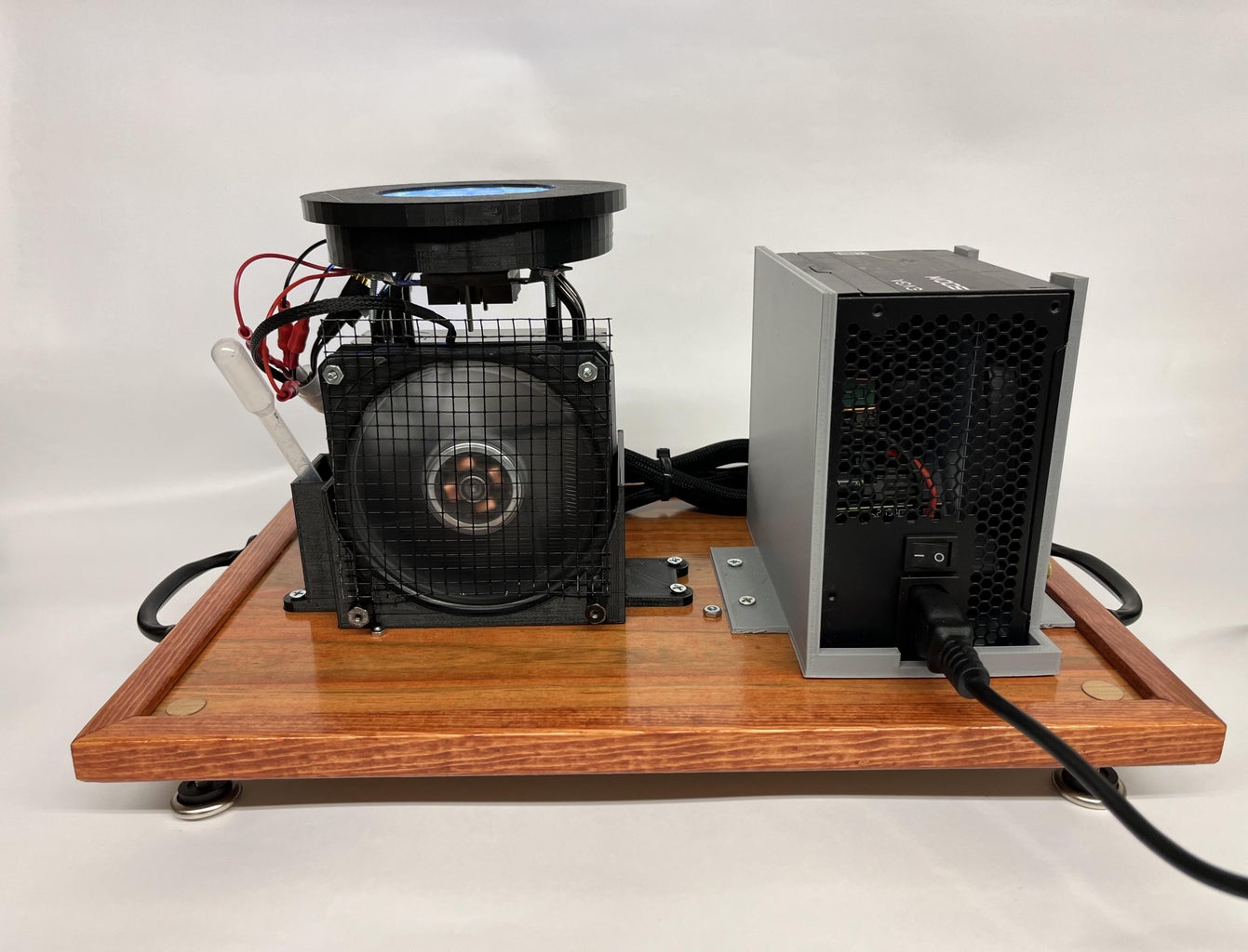
Here we present our version of a Petri-dish-powered cloud chamber that we have incrementally developed at Siena College over the last 10 years, with the help of many students and non-students alike!
The initial design was based off of this Instructables from Nothing Labs.
Supplies
Materials:
- Wood 16in x 11in (Plywood- must cut down to proper size) https://www.lowes.com/pd/1-4-in-Common-P...
- 500 W power supply https://www.amazon.com/EVGA-WHITE-Warranty-Supply-...
- OR MENTION 750 W versuib gere
- Hyper 212 RGB CPU Air Cooler https://www.amazon.com/Cooler-Master-RR-212S-20PC-...
- 12709 peltier https://www.amazon.com/SMAKN%C2%AE-TEC1-12709-Ther...
- 12710 peltier https://www.amazon.com/TEC1-12710-Thermoelectric-C...
- 7g arctic silver thermal paste https://www.amazon.com/Arctic-Silver-AS5-3-5G-Ther...
- 100mm petri dish https://www.amazon.com/Disposable-Petri-Dish-35mm-...
- 3/4" diameter black flex tubing https://www.amazon.com/Split-Tubing-Conduit-Flexib...
- 3.5" square of chamois https://www.amazon.com/AmazonBasics-Drying-Chamois-...
- 24 pin colored adapter https://www.amazon.com/CERRXIAN-Power-Supply-Adap...
- 13" LED string lights https://www.amazon.com/dp/B08MX9RSL9/ref=sspa_dk_d...
- Handles https://www.homedepot.com/p/Everbilt-4-7-8-in-Blac...
- 2 - #4-40 x 1" oval head Phillips screws https://www.homedepot.com/p/4-40-x-1-in-Combo-Round-H...
- 1" cable clamp https://www.amazon.com/Cable-Lokman-Stainless-Rubb...
- 1/2" clamp https://www.amazon.com/LOKMAN-Stainless-Cushioned-...
- Red bullet plug wire connectors https://www.amazon.com/Male-Female-Solderless-Conn...
- Black spray paint https://www.walmart.com/ip/Black-Rust-Oleum-Americ...
- Brown edging https://www.lowes.com/pd/KidKusion-Edge-Cushion/46... (Optional)
- Optional edging:
- Rubber https://www.lowes.com/pd/KidKusion-Corn...
- WOOD
- 8 - #8 x 3/4" flat phillips screws https://www.homedepot.com/p/Everbilt-8-x-3-4-in-Ph...
- 4 - #6-32 x 1" flat head phillips screws -https://www.homedepot.com/p/6-32-x-1-in-Phillips-Flat-Head-Zinc-Plated-Machine-Screw-8-Pack-803691/204274660
- Brown stain https://www.homedepot.com/p/Varathane-1-qt-Dark-Wa... (Optional)
- Electrical tape https://www.lowes.com/pd/Scotch-700-Electrical-Tap...
- Isopropyl Alcohol https://www.amazon.com/Amazon-Brand-Isopropyl-Al...
- Super Glue https://www.amazon.com/Loctite-Control-4-Gram-Bott... (Optional)
- Adjustable Feet https://www.homedepot.com/p/Everbilt-1-1-16-in-Threaded-Gl
Tools:
- Solder/soldering equipment
- Ruler
- Wire cutters/wire strippers
- Drill
- Screwdriver
- Pipette
- Pencil
- Scissors
- Crimper
* Suggested product to buy


Step 1: Prepping the Board for Feet
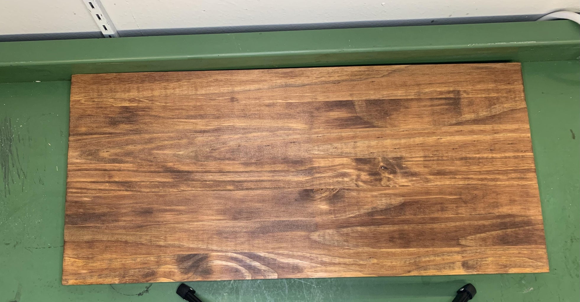
The first thing to do is to prep a wooden board to use as the base to mount all the subcomponents on. You can use any type of wood, but we have had good luck with 1/2"-thick plywood.
- Cut your board to 18" x 12". This is a good size that keeps things small enough to be portable, but big enough to allow some bending and crimping of the cables.
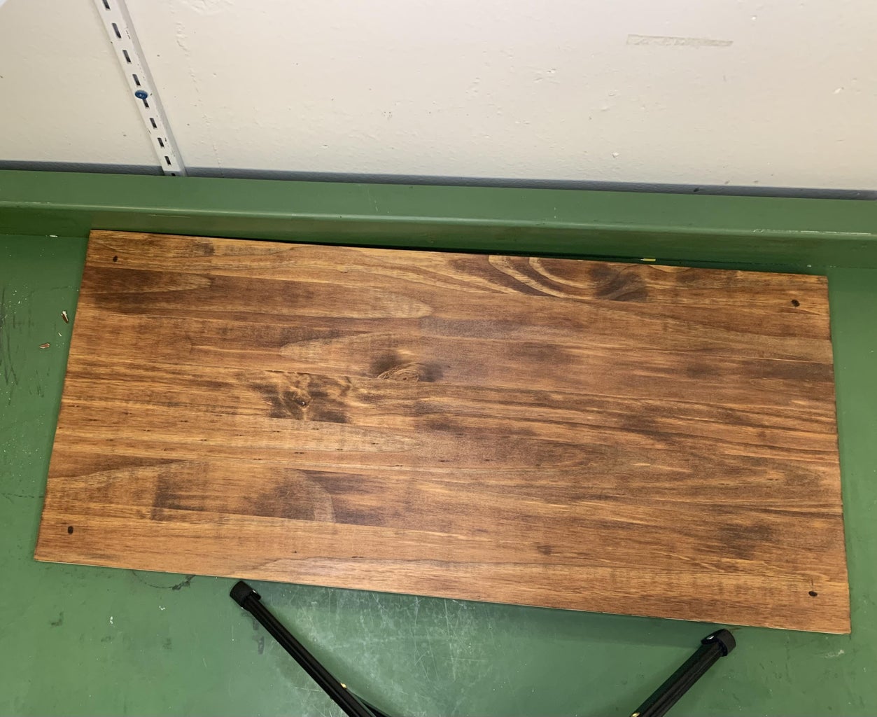
- Optional! Stain it if you like! We have been using a basic brown that brings out the details in the wood.
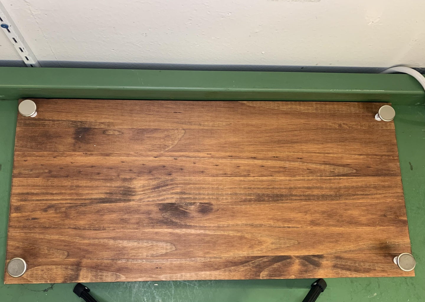
- At each corner of the board measure 1" away horizontally then 1" vertically and mark a dot as in the picture
- Depending on the type of feet you get, pay attention to the drill bit it instructs you to use. This will help you have the feet secure in the board
Step 2: Optional...but Helpful! Place Edging Around the Board
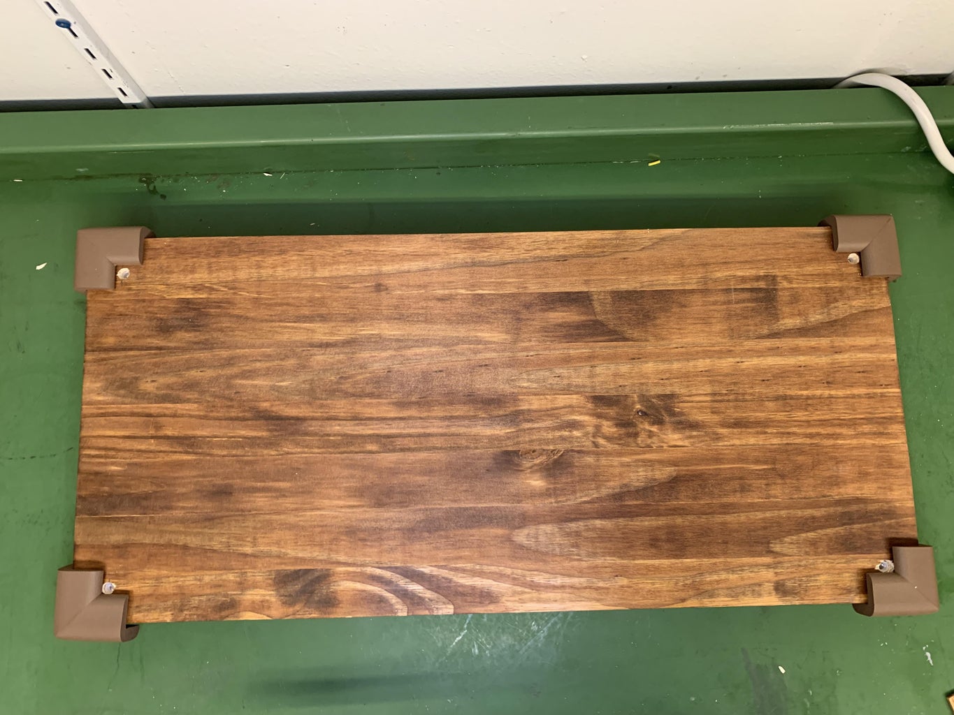
Totally up to you, but we usually put some sort of edging/molding around the board, in part to prevent splinters. We have done this with wood, but you can also just use some rubber trim that is used to babyproof rooms.
- Grab your corner edging, place hot glue on the side and top of the board, place the corner firmly on the hot glue. Repeat this process for all the corners
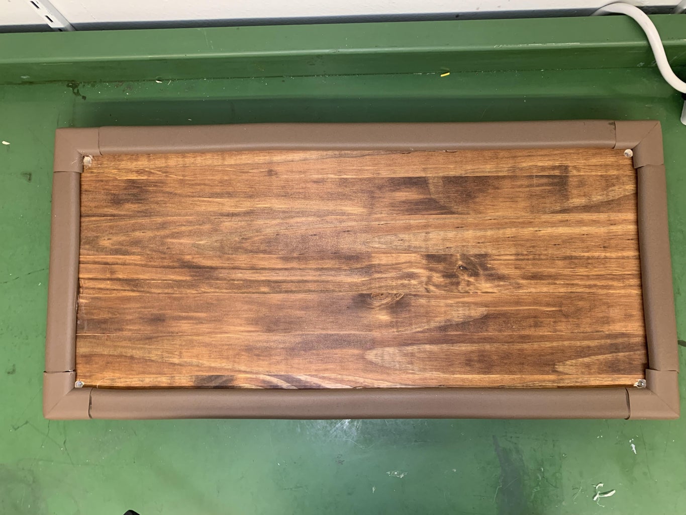
- Grab the 52.5 cm trim, place hot glue on the side and top of the board, place the the edging firmly on the hot glue. Repeat this process for the other 52.5 cm trim
- Grab the 20 cm trim, place hot glue on the side and top of the board, place the the edging firmly on the hot glue. Repeat this process for the other 20 cm trim
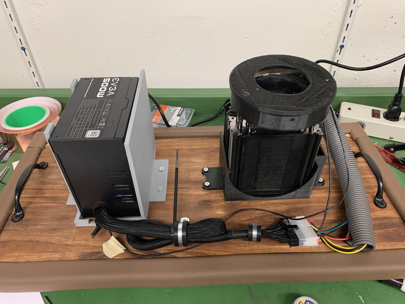
Step 3: Marking Holes to Drill
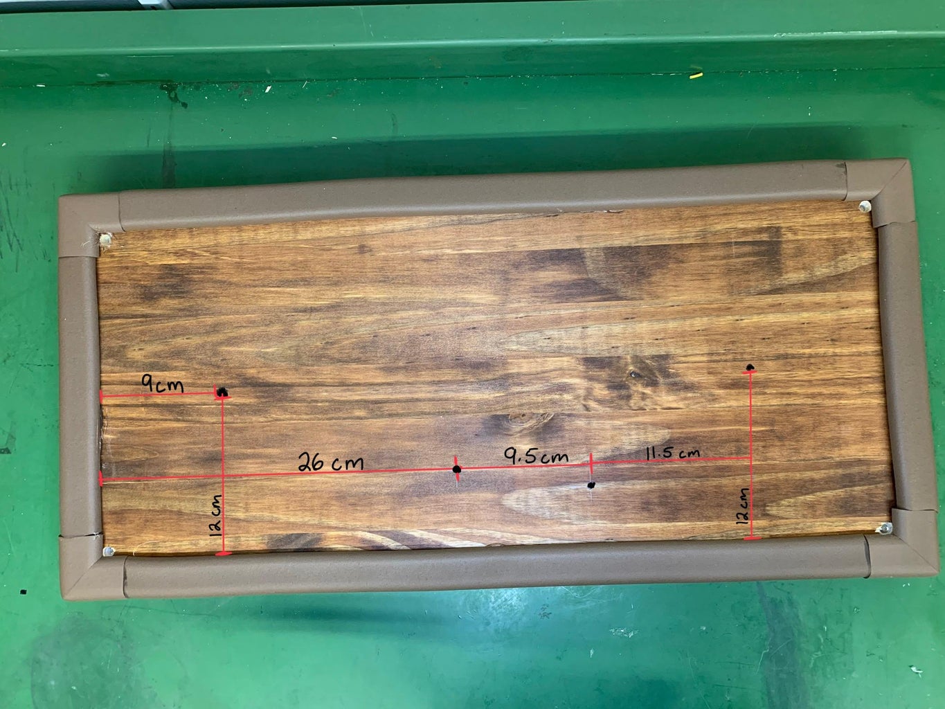
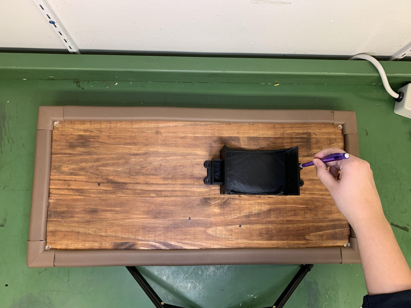
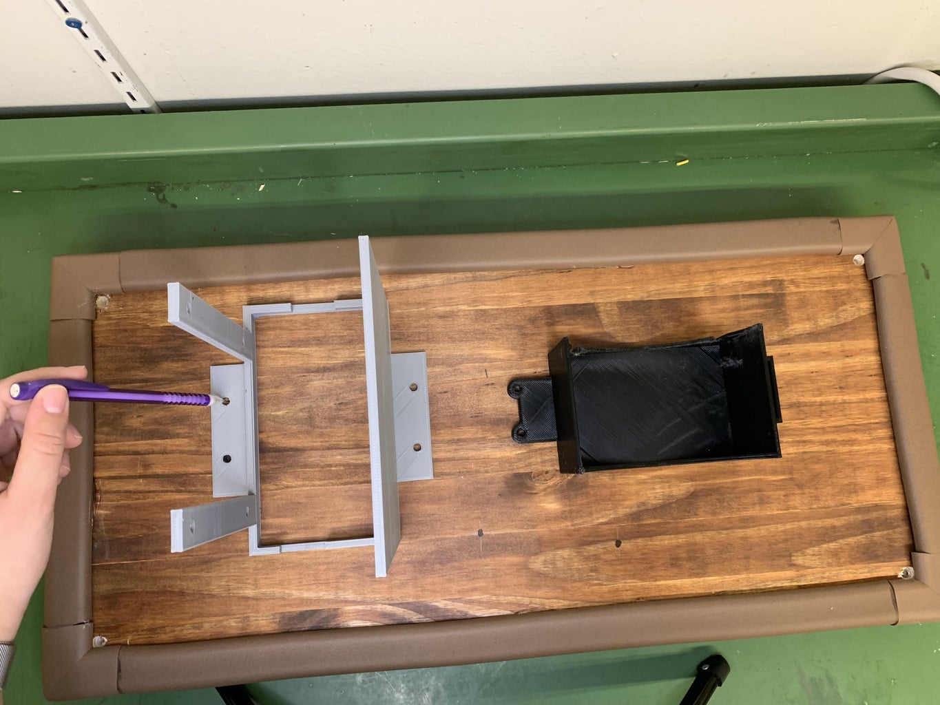
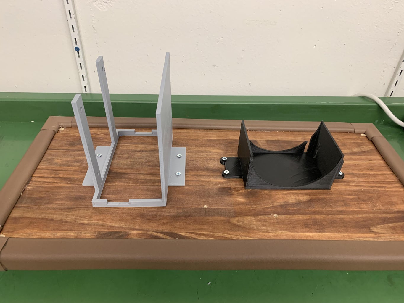
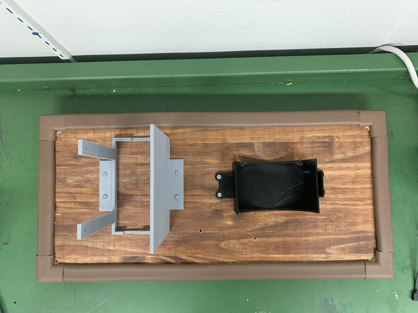
- Please look at the first picture to see the measurements where to mark dots where we want to drill holes.
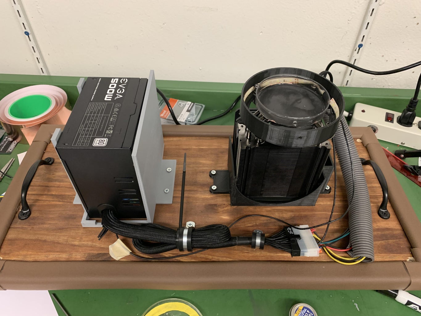
- Grab the Hyper 212 3D printed part. Place the bottom right hole on the 3D printed part on the marked spot thats closest to the right side of the board. Take a pencil and mark each hole on the board.
- Grab the 500 W power source 3D printed part. Place the bottom left hole on the 3D printed part on the marked spot thats closest to the left side of the board. Take a pencil and mark each hole on the board.
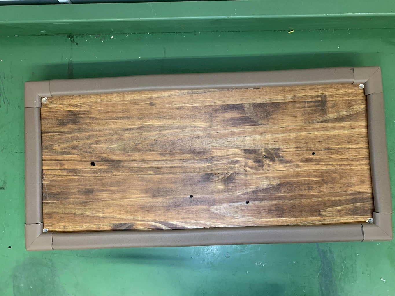
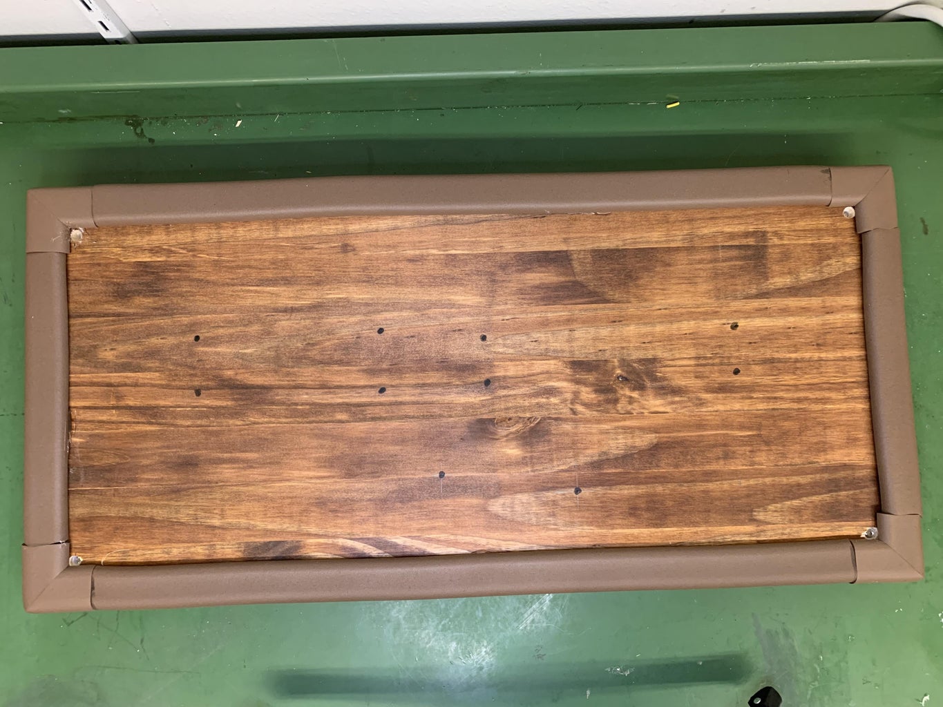
- You will now have a board that looks like the last picture ready to be drilled.
Step 4: Drill Holes on Board and Attach 3D Part Into Board
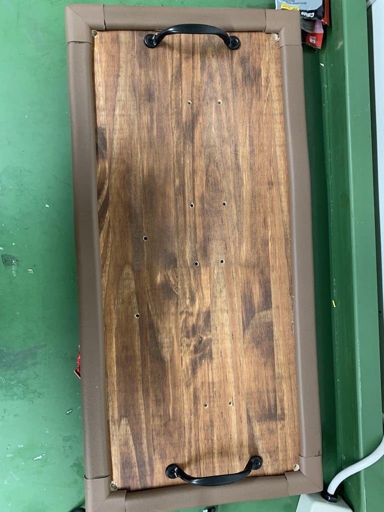
- Use a hand drill or drill press with a small drill bit and drill holes at each marked spot
- Take the #8 x 3/4 IN wood screws and screw in the 3D printed parts for both the Hyper 212 and power source in the board
- Grab the black handles and place one on each side of the board. Try to center them as best as you can. Mark the holes, drill, and screw into the board.
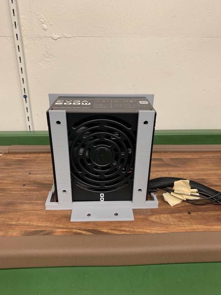
- Attach the power supply to the 3D printed part by screwing in with 1-1/4" x 8 screws into the power supply
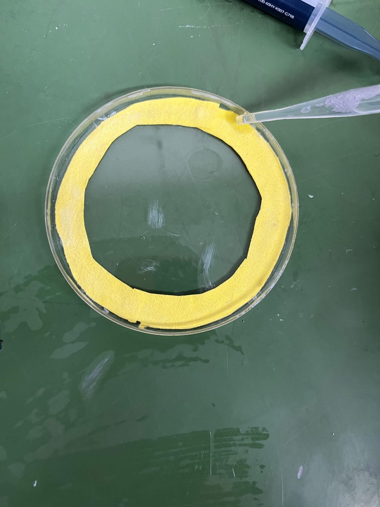
Step 5: Preparing Petri Dish
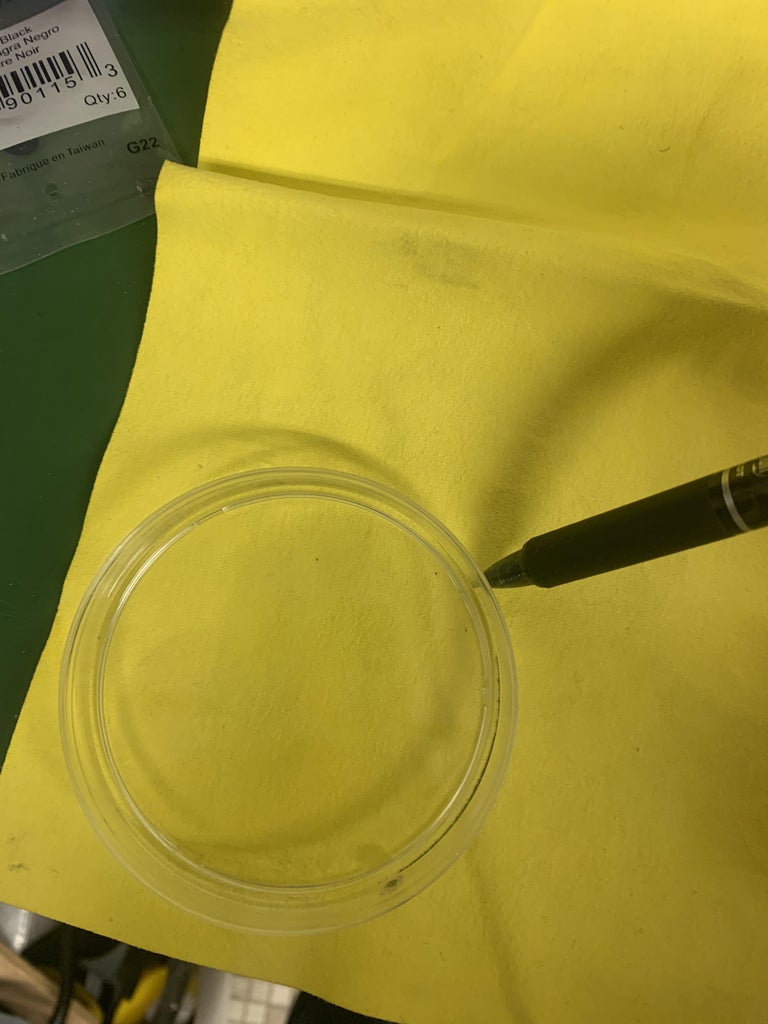
- Grab your petri dish. Paint the outside of the petri dish black
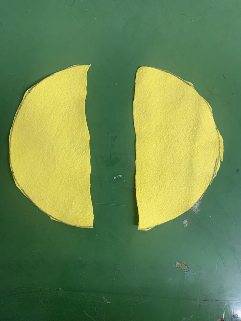
- Use the base of the petri dish to trace a circle, using a pencil. Cut the circle out. Cut the chamois cloth circle directly in half
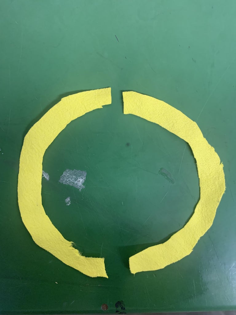
- Now cut smaller half circles out of the half circles you already have, creating two rainbow shaped arcs, about a 1/4" thick.
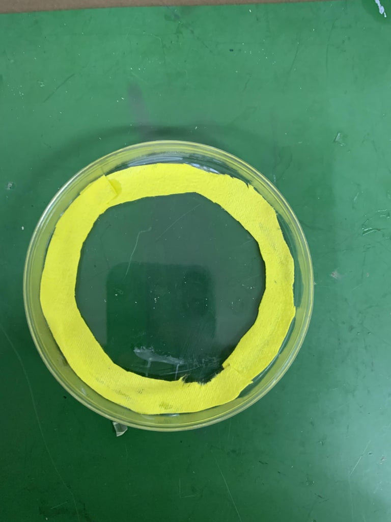
- Use super glue and a paint brush to paint the glue on the arcs and place along the edge of the inside of the lid of the petri dish.
- Be very careful when using the epoxy cement to assure no extra glue gets on the petri dish, it will obstruct viewing.
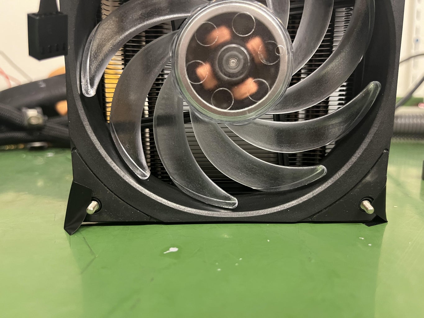
Step 6: Prepping Cooling Fan
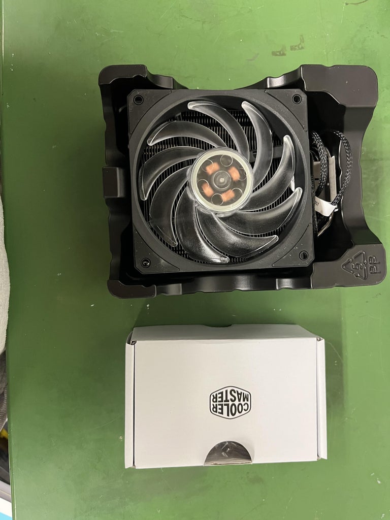
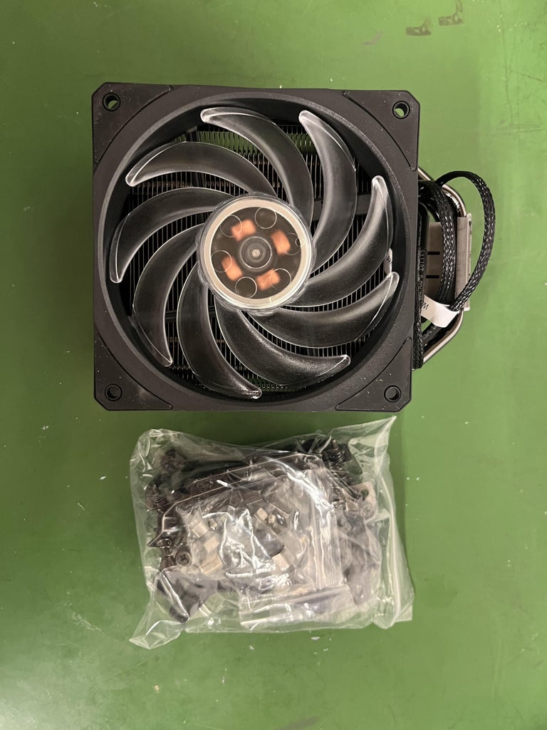
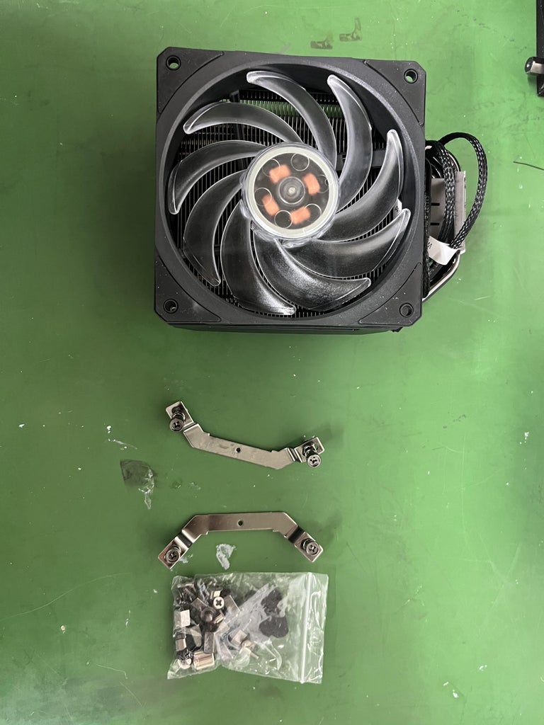
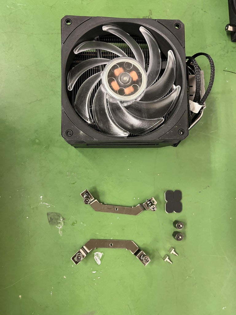
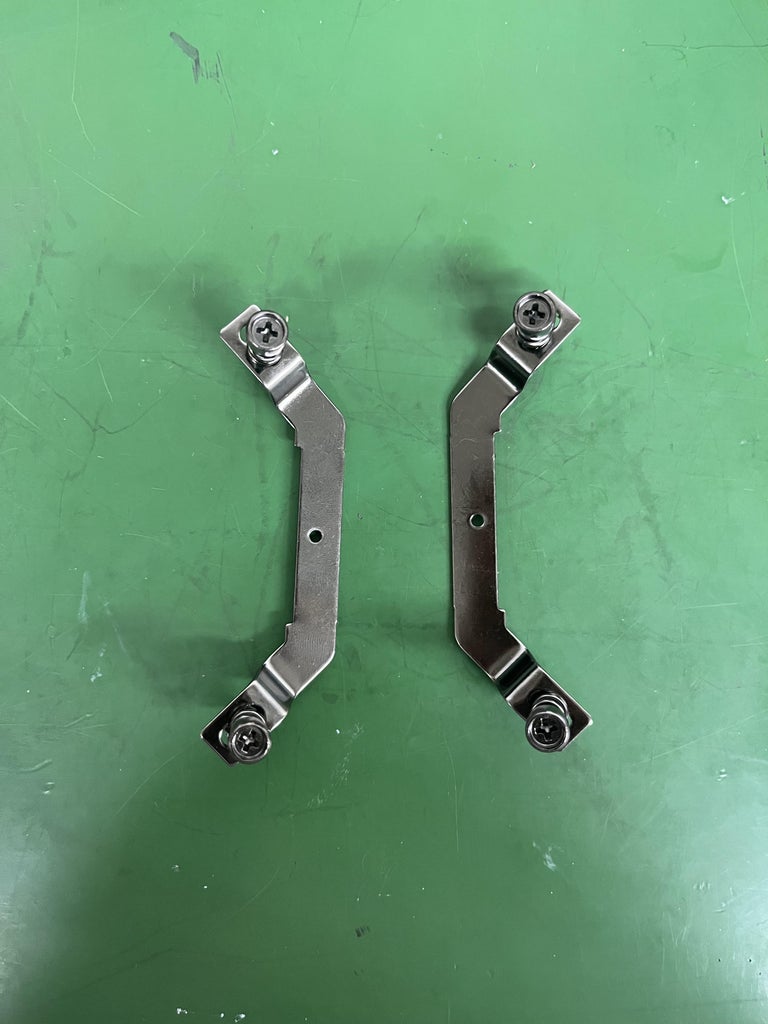
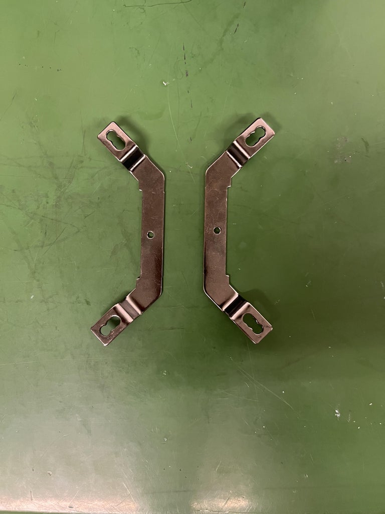

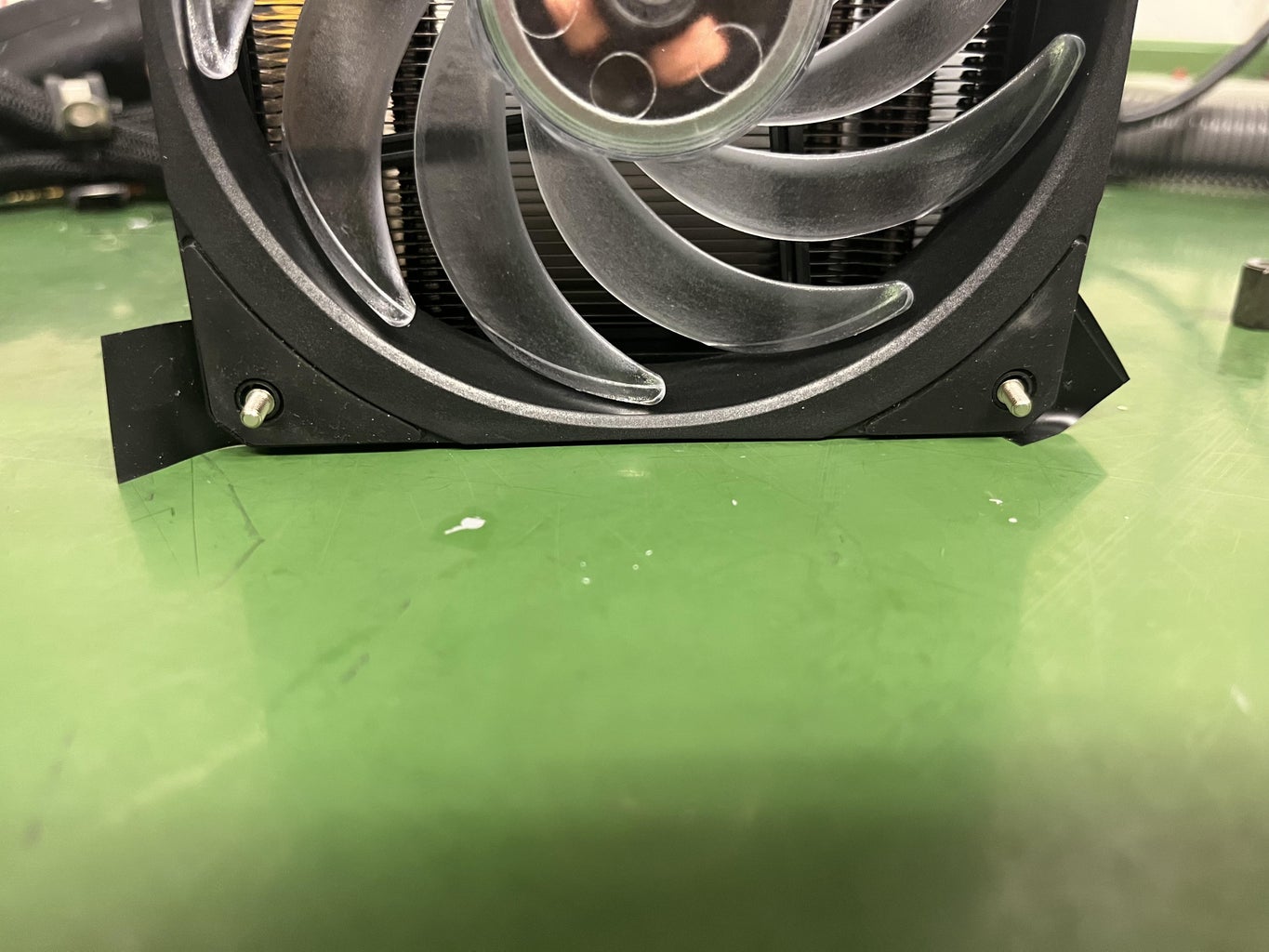
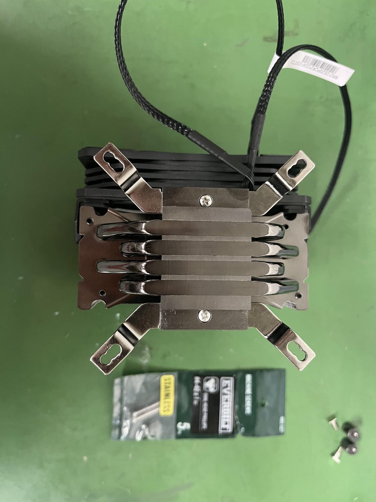
- In the Hyper 212 box there will be the fan and a white box. In the white box there are several bags of extra screws and parts. Go through these bags and find the parts as seen in the pictures above.
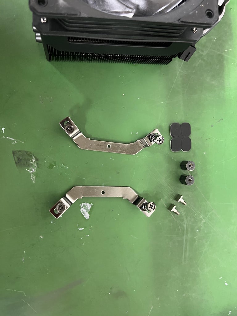
- Grab the metal angled parts. Grab some sharp pliers and rip off the screw attached to the part. Above is a video to show the best away to detach the screw from the metal part.
- Grab the 2 - #4-40 x 1" oval head phillip screws. Place the angle metal part beneath the holes. Screw in the #4-40 x 1" oval heads on each side. Secure with a bolt. Reference to the pictures above.
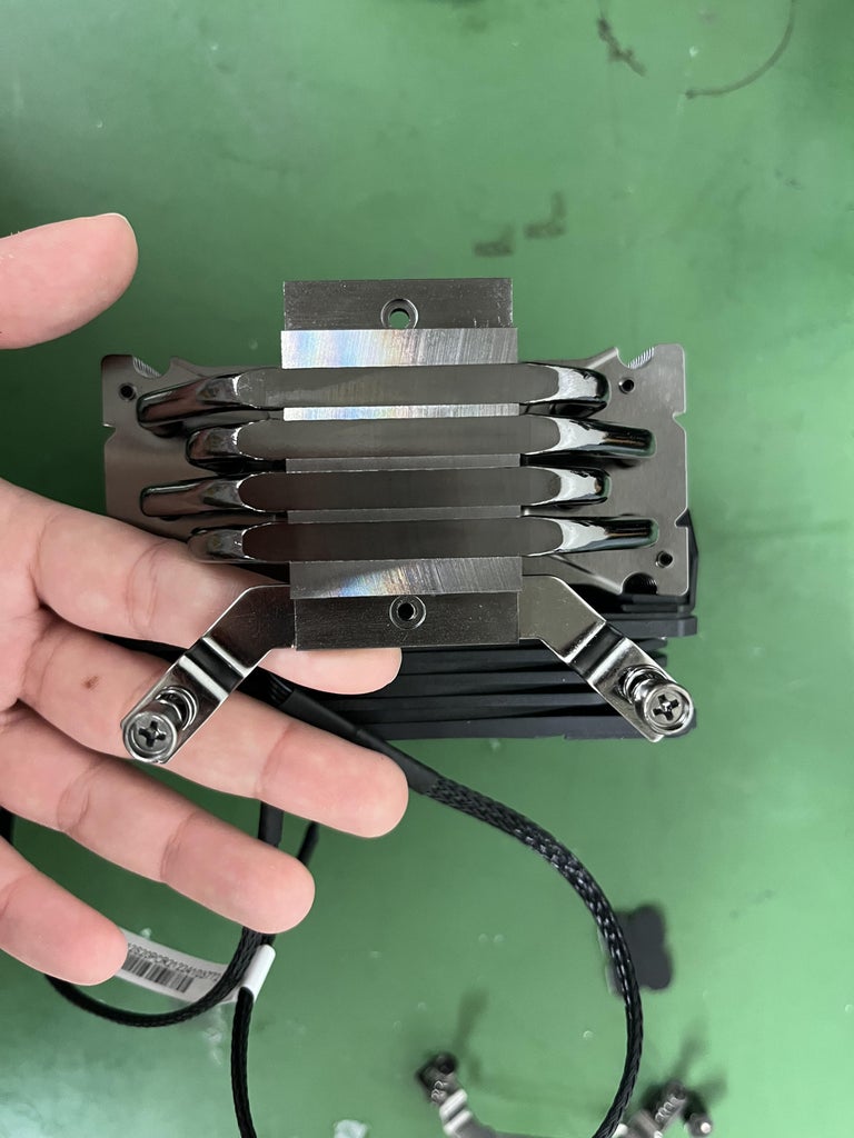
- Grab two of the #6-32 x 1/2" screws and place the screws in the bottom left and right holes of the fan so that the screw is coming out of the Hyper 212. Grab some tape and tape the back of the screw to the Hyper 212. Now take the Hyper 212 and slide the fan into the 3D printed part. Take the "washer" and twist onto the screws to secure the fan into the 3D printed part.
- Take 4 of the #8 x 3/4" flat Phillips screws, and screw the 3D printed Hyper 212 cooling fan part into the board.
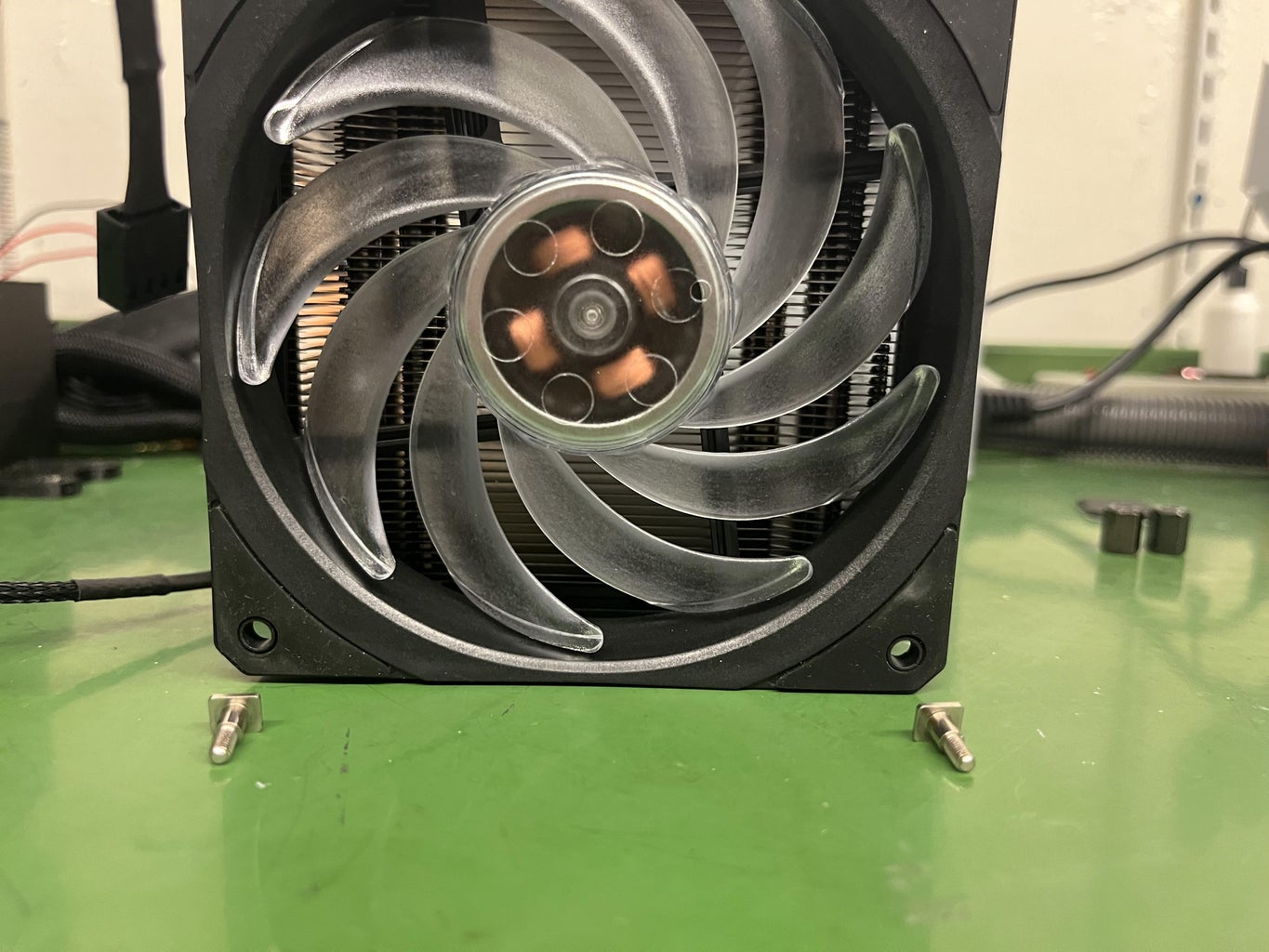
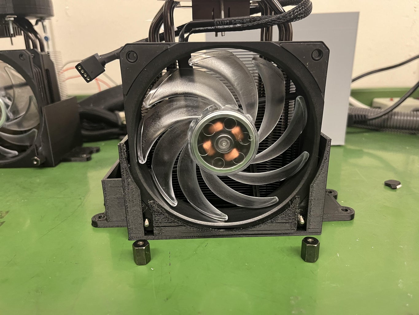
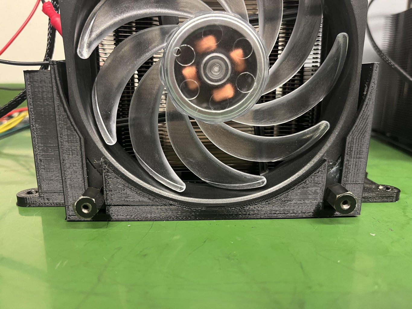
Step 7: Place 3D Printed Part Onto Hyper 212 Fan
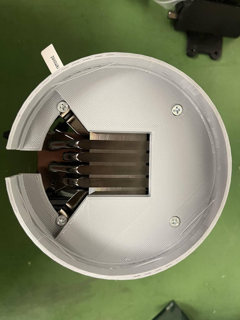
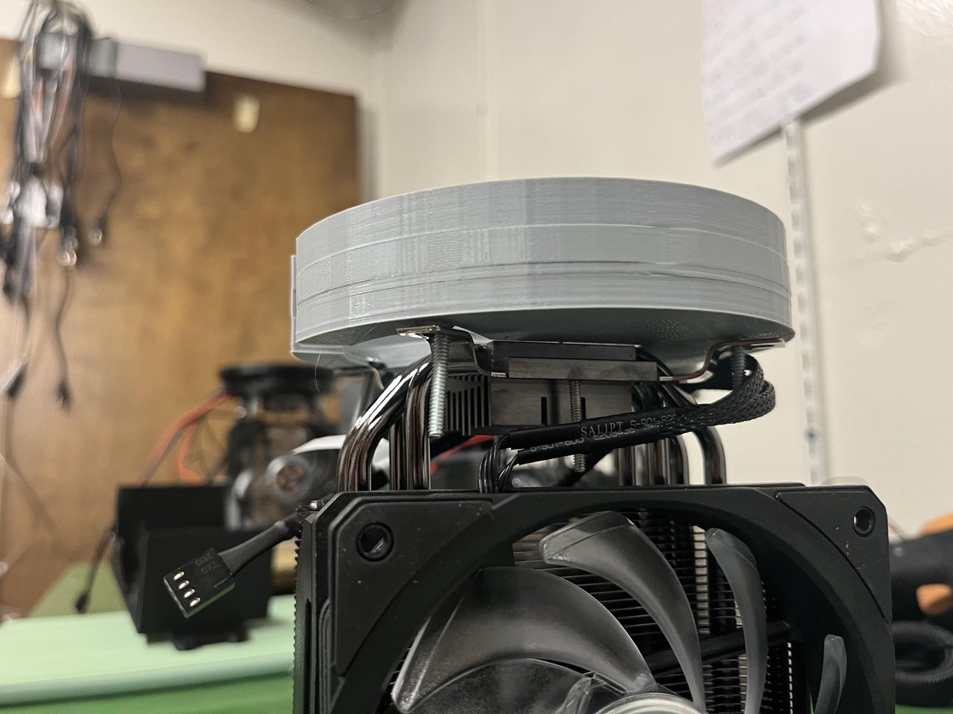
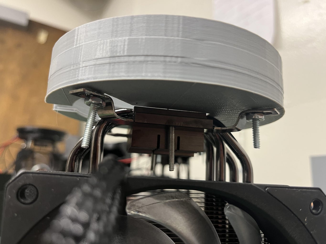
- Align the circle Hyper 212 fan to the holes of the angled parts
- Take 4 - #6-32 x 1" flat head phillips screws and place them through the holes.
- Take the washers and secure the the screw to the 3D printed part
*Reference to the pictures above*
Step 8: Converting Power Supply
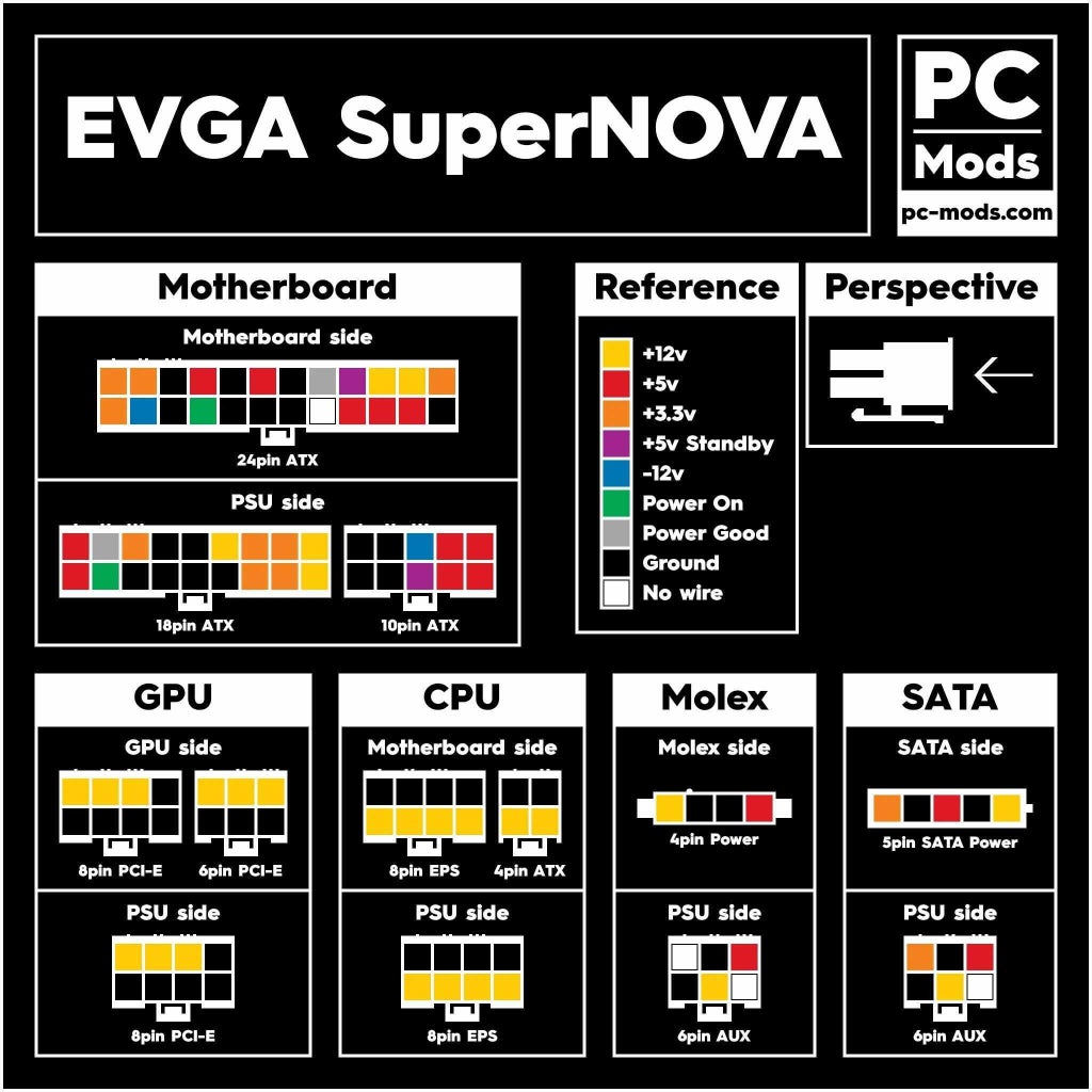
It can be a challenge connecting the wires from the Peltiers and the cooling fan to the proper connections coming from the power supply. It used to be that EVGA used colored cables that went into the 24-pin output, however they changed to all black cables...which could be troublesome at times. :)
Additionally, we wanted an easy way that people could swap out power supplies, if they were so inclined.
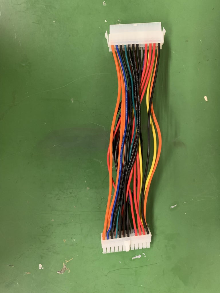
To this end, we decided to make use of 24-pin connectors that we could have all the wires from the Peltiers and cooling fans, and then we could just plug the connector into the power supply connector.
In the instructions below, we are making use of a particular connector we ordered LINK GOES HERE with very specific wire colors. If you make use of a different connector, that's fine, but remember that the colors are not the important thing...its making sure that whatever needs 12 V goes to a 12 V pin and whatever needs 5 V goes to a 5 V pin, etc.
- Find the 24 pin adapter on the power supply and the 24 pin connector. Connect the 24 pin adapter on the power supply and the 24 pin connector together.
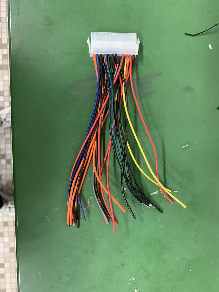
- Now the 24 pin adapter is connected grab the following wires:
- 5 Black wires (ground)
- 2 Yellow wires (12 V)
- 1 Red wire (5 V)
- 1 Green wire (power supply ON)
- It doesn't matter which black wires you use or which yellow wires you use. For the displayed connector, they all carry the same voltage.
- Label the new wires you just grabbed: Black 1-5, Yellow 1-2, Red, and Green 1
- Make sure to cut off the plastic part of the 24-pin connector that isn't attached to the power supply
- After labeling all the wires, you can cut the rest of the wires away once the cloud chamber is assembled. Don't do it just yet! Just in case you have made a mistake and need to use different wires.
Step 9: Converting Power Supply (continued)
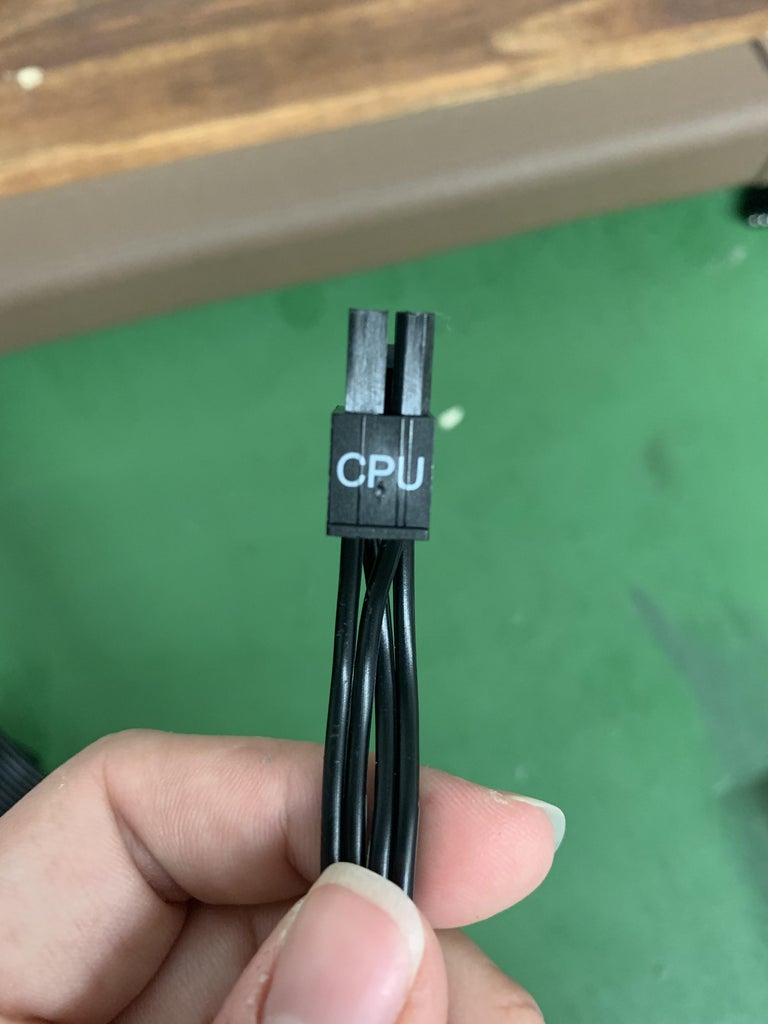
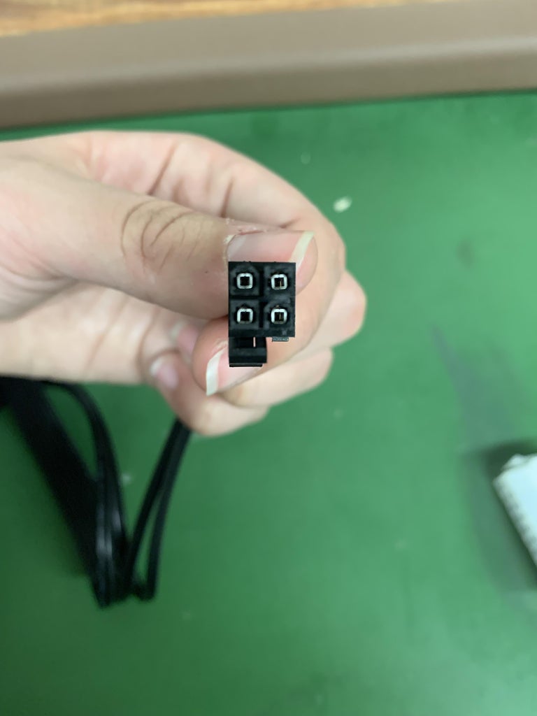
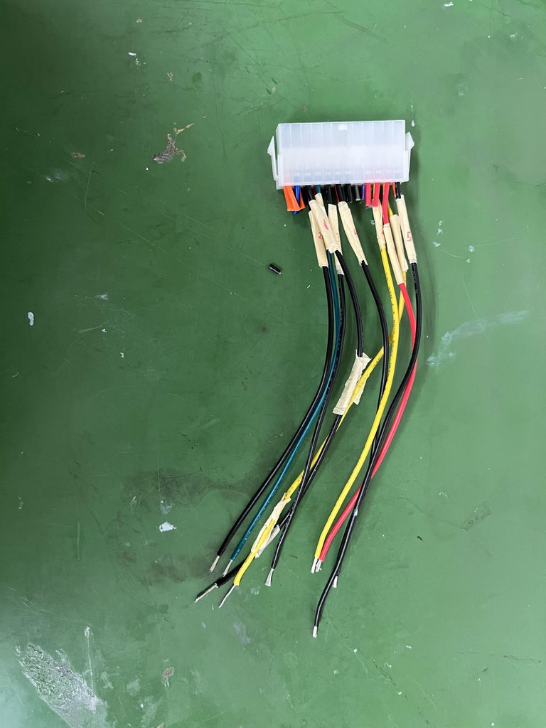
- Grab the CPU wires attached to the power supply and orient it in the position shown in picture 1 for the 4-pin ATX.
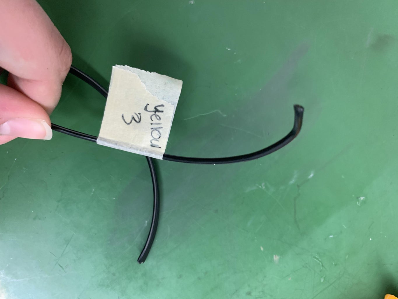
- Grab and label one Yellow wire from the CPU as Yellow wire 3. This wire will be included with the other two yellow wires from the power supply.
Step 10: Connecting/soldering Wires Together
WARNING! It's really important to do this part correctly. If you don't, a) your power supply will not turn on or b) you could brick the power supply.
- Solder the ends of Black wire 2 and Green wire 1 together. Wrap this connection with electrical tape.
- You can check to see if you have done this correctly by plugging in the power supply and turn it on, but don’t let any of the exposed wires touch each other.
- If the fan turns on you have correctly completed this procession and may move on, but if the fan does not turn on check your soldered wires and make sure no exposed wires are touching.
Make sure this section all works before proceeding further.
If you find the power supply has not turned on and you go to fix things, before trying it again, unplug and then plug back in the 24-pin connector. We think that there is some sort of "reset" that happens when we do that, but we're not entirely sure why. :)
Step 11: Connect Hyper 212 Cooling Fan to Power Supply
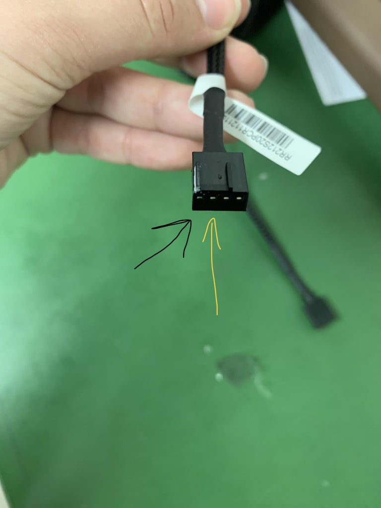
- Look at the 24 pin connector and pick out Black wire 1 and Yellow wire 1, setting the other wires to the side. Also, pick out two thinner wires of any color in the given small bag.
- It may be helpful to pick out a black wire for Black wire 1 to keep it and Yellow wire 2 different colors, but it is not necessary. Thin wires of any color will do.
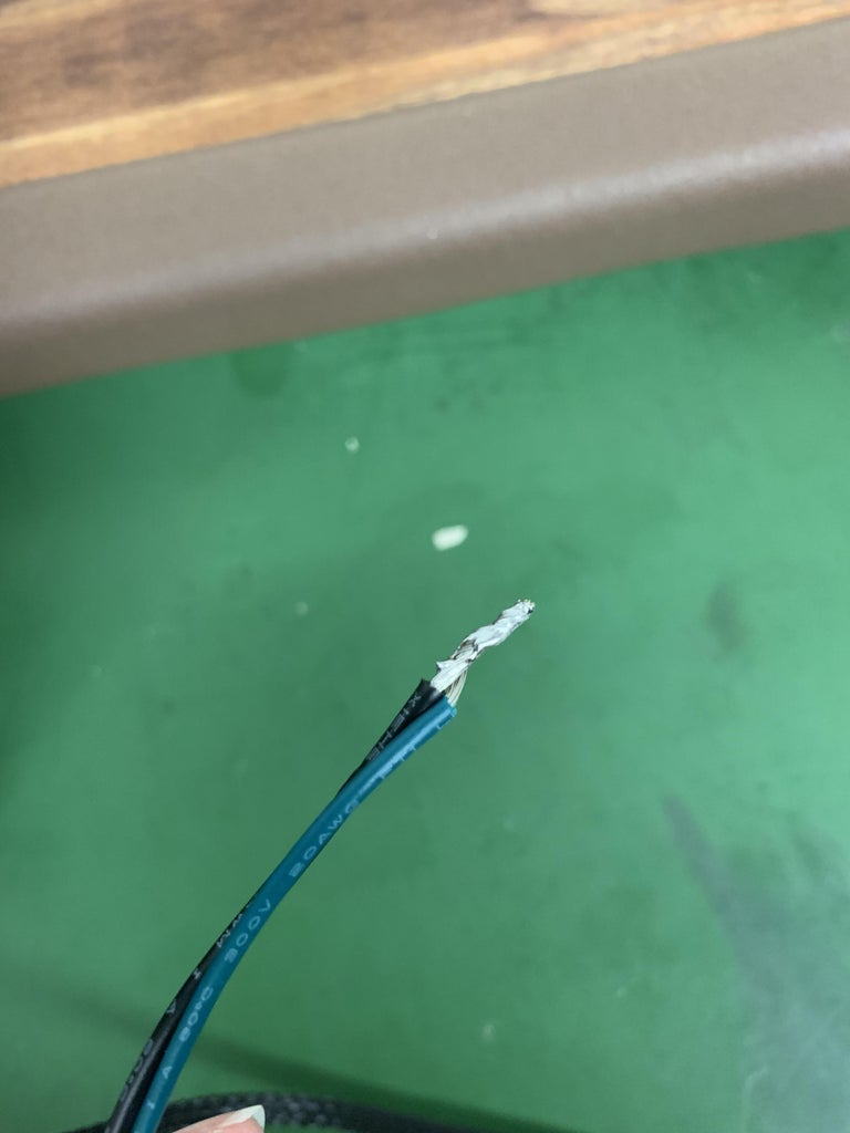
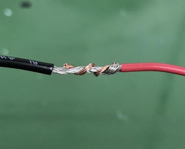
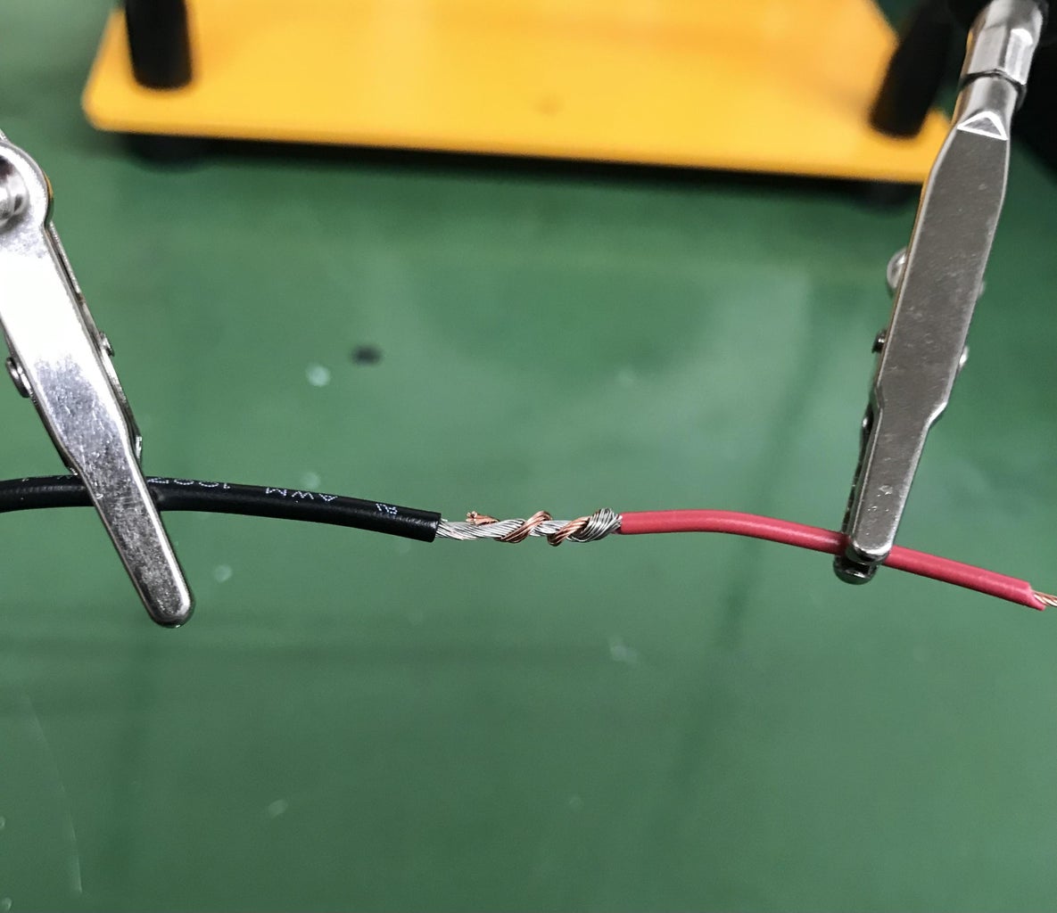
- Strip the two thin wires on both ends. One end should be stripped about ½ an inch off while the other end can be stripped about an inch off. To twist the wires together, grip the bare wires at the base, where the rubber begins. Twist the wire while pulling it slowly through your pinched fingers until all of the bare wires are twisted together and form a single point. Strip about an inch off the ends of Black wire 1 and Yellow wire 1 as well, and twist the bare wires on each as you did with the thin wires.
- Grab black wire 1 and one of the thin wires. Hold the wires so that both of the bare wire twists are facing each other. Use the end of the thin wire that is stripped about ½ inch. Bringing the tips of the twists to the rubber base, wind one wire twist around the other. You want to twist these wires together, and you should be left with one straight line or wire.
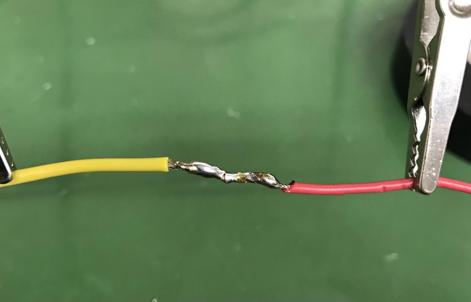
- Secure these wires so that you can solder them. We recommend the use of a soldering clamp stand (Such as https://www.amazon.com/Helping-Soldering-Workshop-Non-slip-Weighted/dp/B07MDKXNPC/ref=sr_1_8?crid=3RA5EDOMS33M0&keywords=helping%2Bhands%2Bsolder%2Btool&qid=1686859050&s=instant-video&sprefix=helping%2Bhands%2Bsolder%2Btool%2Cinstant-video%2C72&sr=1-8&th=1)
- Using the holders to keep the wires steady, solder them together. Make sure that every point that the wires make connection in the twist have solder connecting them. You want to ensure that there are no wires sticking up that are not connected and that the solder is on the wires firmly.
- Wrap the solder in electrical tape. Make sure that there are no exposed parts.
- Plug the extended Black wire 1 into the far left slot on the adaptor port connected to the Hyper 212 fan. Plug the extended Yellow wire 1 into the slot directly next to Black wire 1 (middle left).
Warning! Make sure the cooling fan turns on before you proceed! If you hook up the Peltiers in the next step and fan is not working, you can potentially damage the Peltiers.
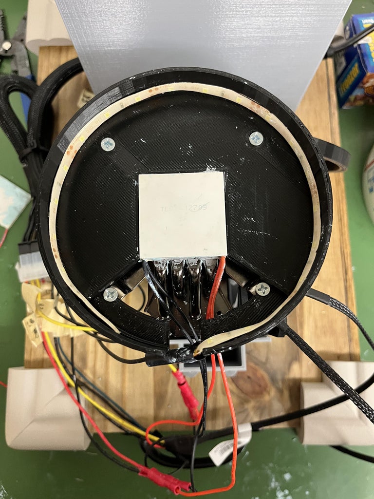
Step 12: Connect Peltiers
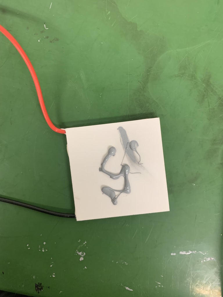
Warning! In this section, you will be instructed to spread thermal paste on the Peltiers. This is a step which can greatly affect how good your cloud chamber works. Too much thermal paste and it can become insulating. Not enough thermal paste and you won't get the environment cool enough.
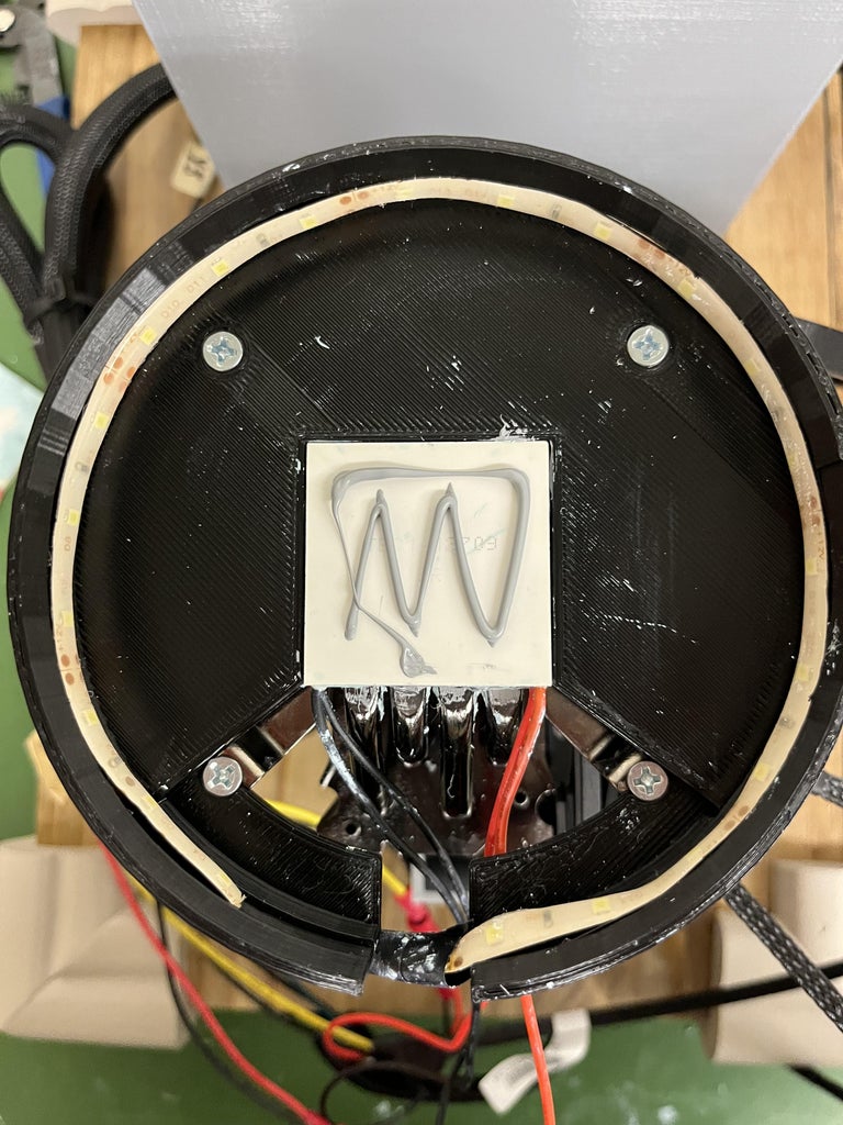
We recommend applying the paste to the bottom of the Peltiers, make it cover the whole Peltier but thin enough such that if you just lightly scrape the applied paste you can see the Peltier itself.
When applying the paste to the top of the 709 (the part that touches the petri dish), apply roughly double the amount you had been. This should still be a relatively small amount.
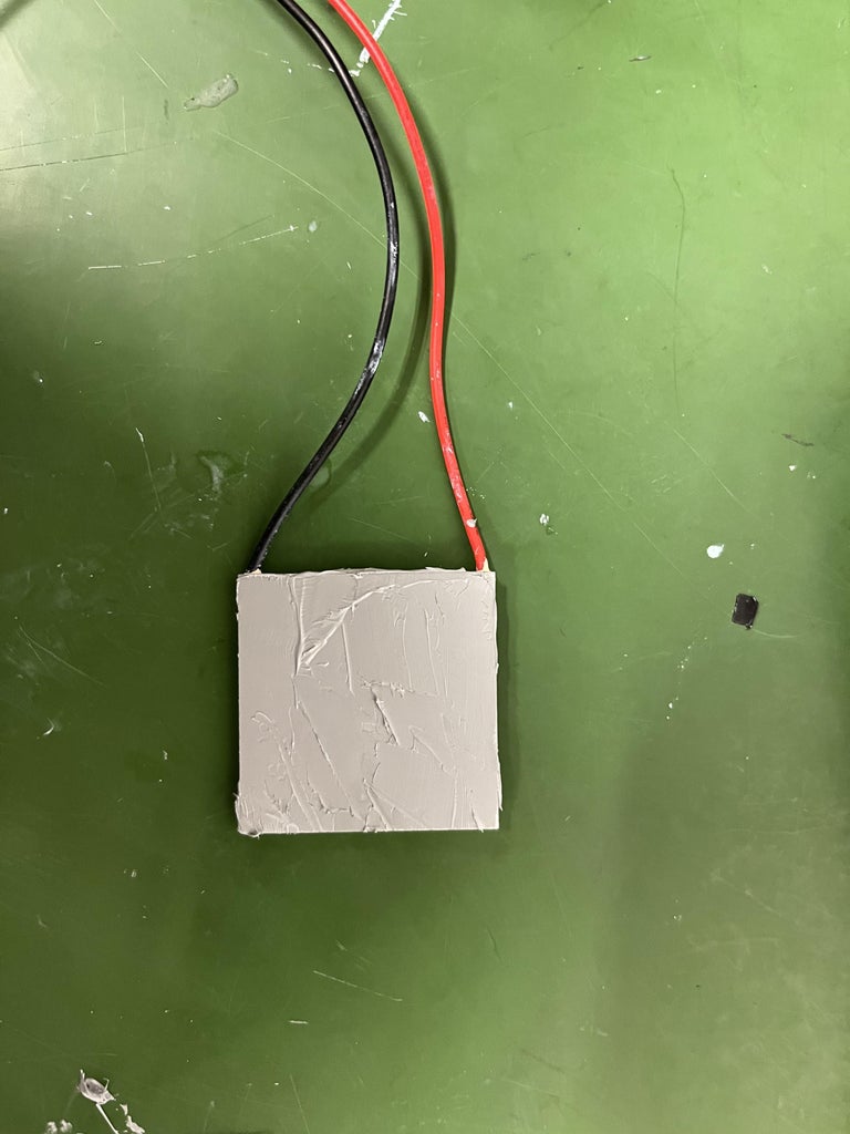
In all cases, make sure the thermal paste is smooth and not bumpy or clumpy. If it is not smooth, we have found that it can negatively affect the heat transfer.
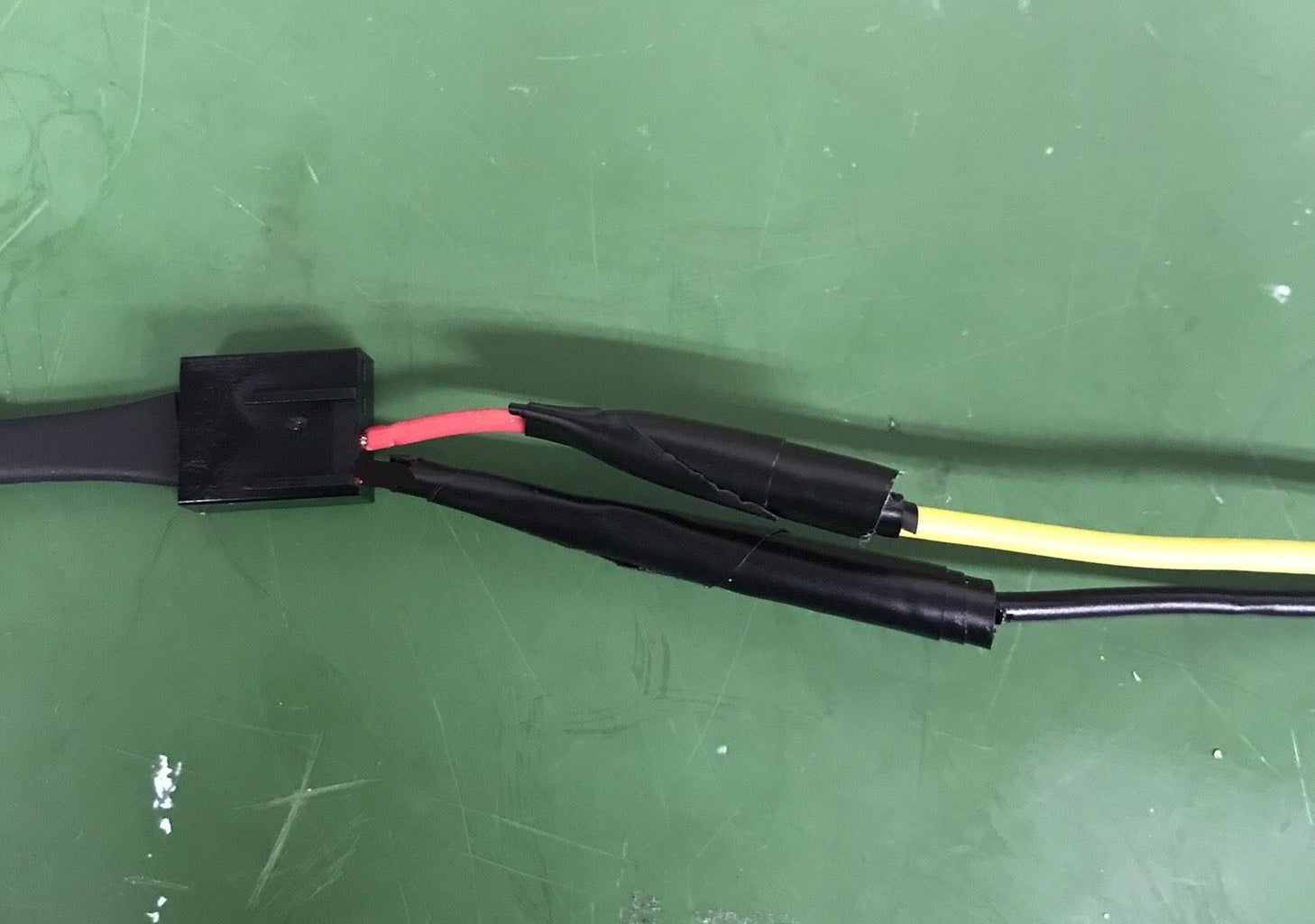
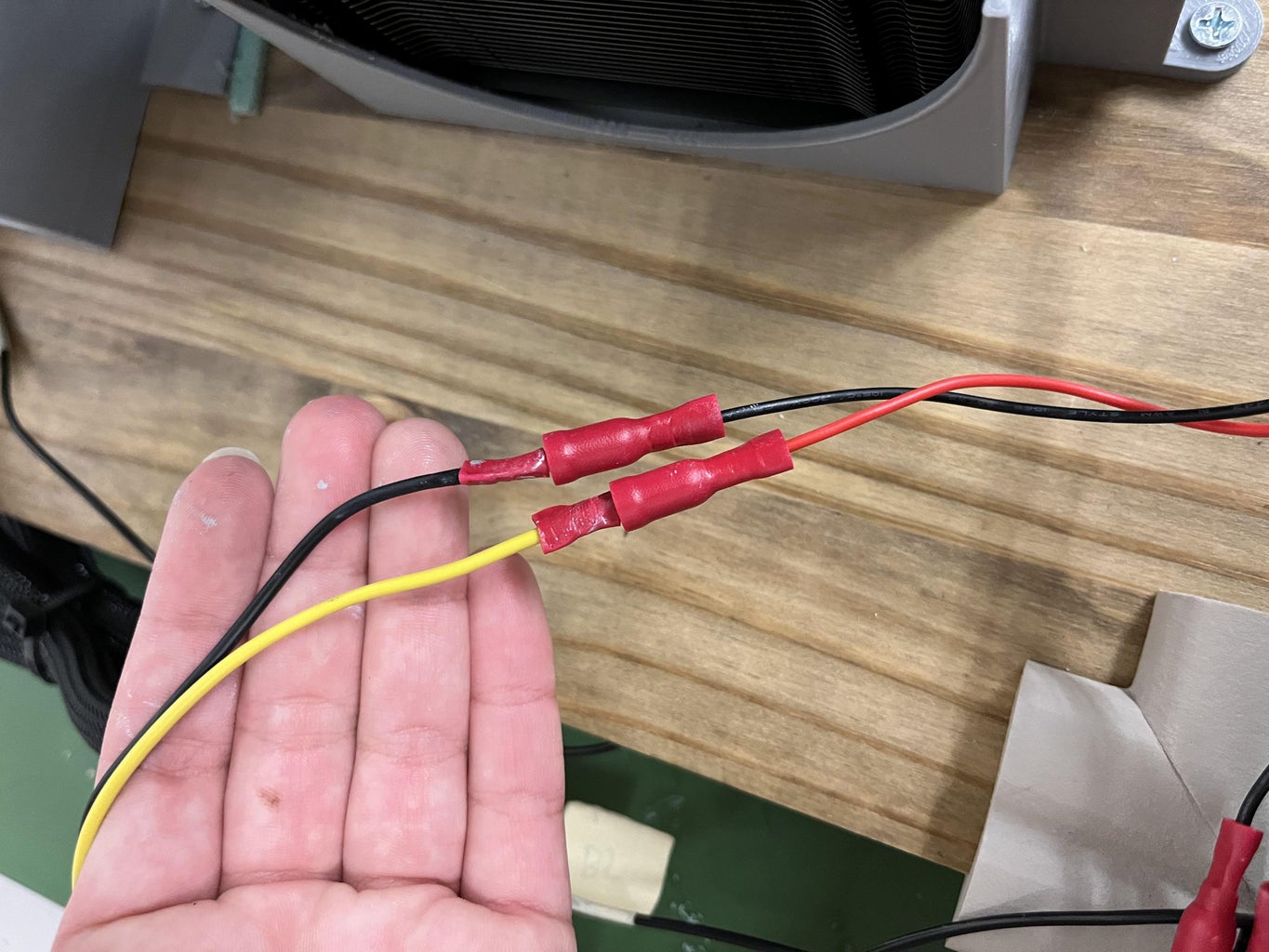
- Take your Peltiers, one 710 and one 709. Strip each wire half and inch.
- Grab the 710 Peltier. Position it with the black wire on the left and the red wire on the right. Grab the red wire from the Pelter and Yellow wire 2. Using the insulated wire connectors, connect the red wire and yellow wire 2 together.
- Grab the black wire from the Pelter and black wire 3. Using the insulated wire connectors, connect the black wire and black wire 3 together.
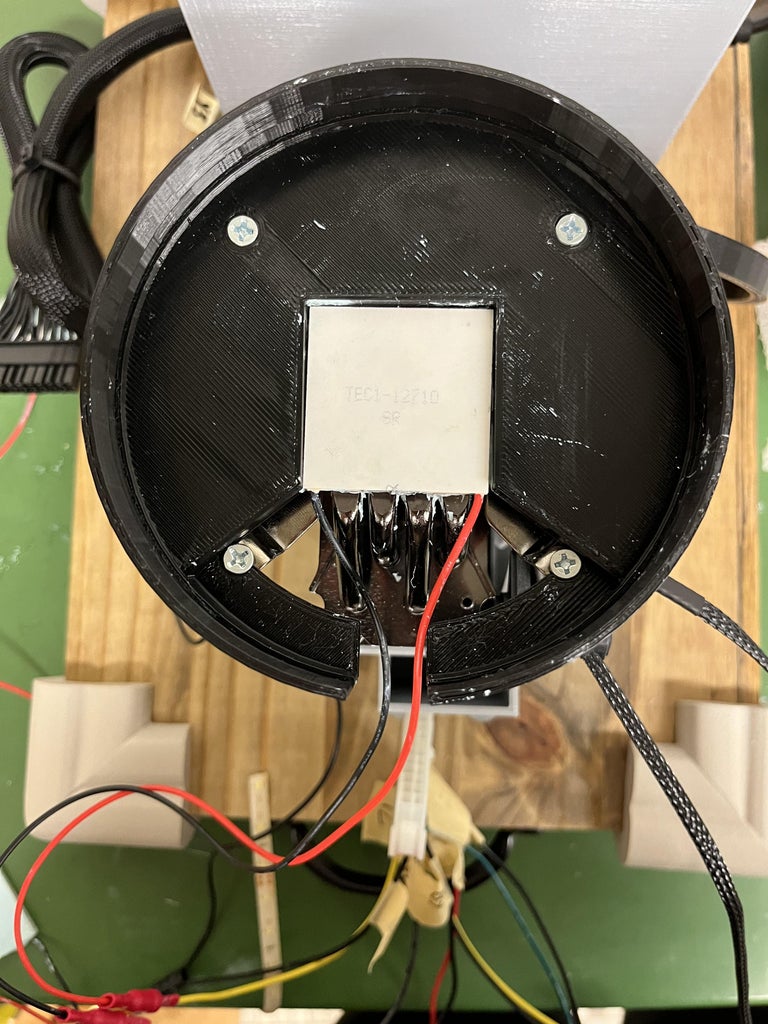
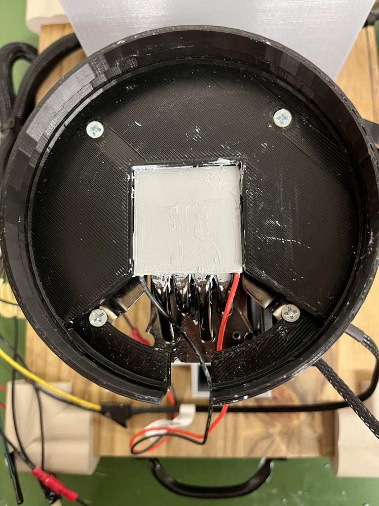
- With the black wire on the left and the red wire on the right, apply a thin, even layer of thermal paste onto the back of the 710 Peltier and spread around the whole surface with a credit card like material. Firmly press the Peltier, thermal paste down, onto the Hyper 212.
- Plug in your power supply with no wires touching and test your Peltier to see if the top of the Peltier is cold, if not flip it over and try again
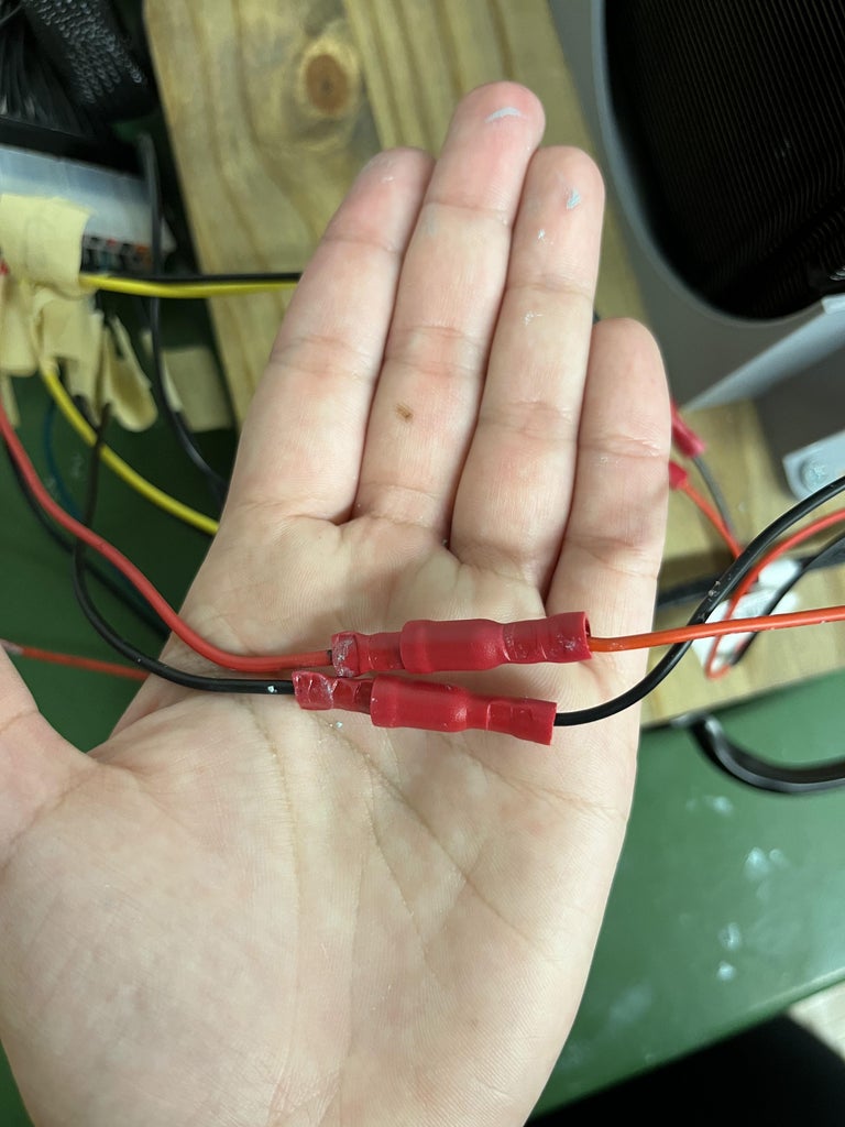
- Grab the 709 Peltier. Position it with the black wire on the left and the red wire on the right. Grab the red wire from the Peltier and red wire 1. Using the insulated wire connectors, connect the red wire and red wire 1 together.
- Grab the black wire from the pelter and black wire 4. Using the insulated wire connectors, connect the black wire and black wire 4 together.
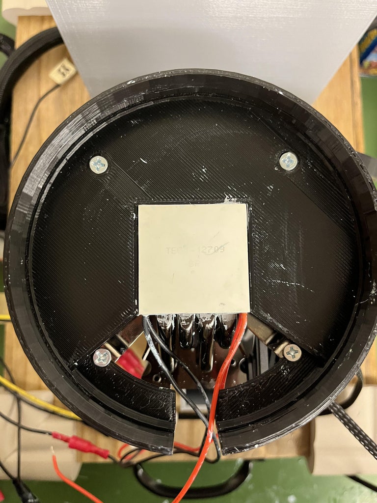
- Apply a thin layer to the top of the 710 Peltier and press the 709 down firmly on top of it with the red wire on the right and the black wire on the left. Plug in the power supply and make sure the top is cold.
Step 13: Connect LEDs
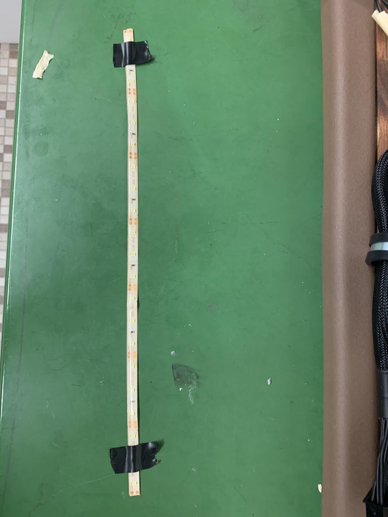
- Take the LED strip lights and cut them to 13" or at a point that is relatively that size where it is instructed for you to cut.
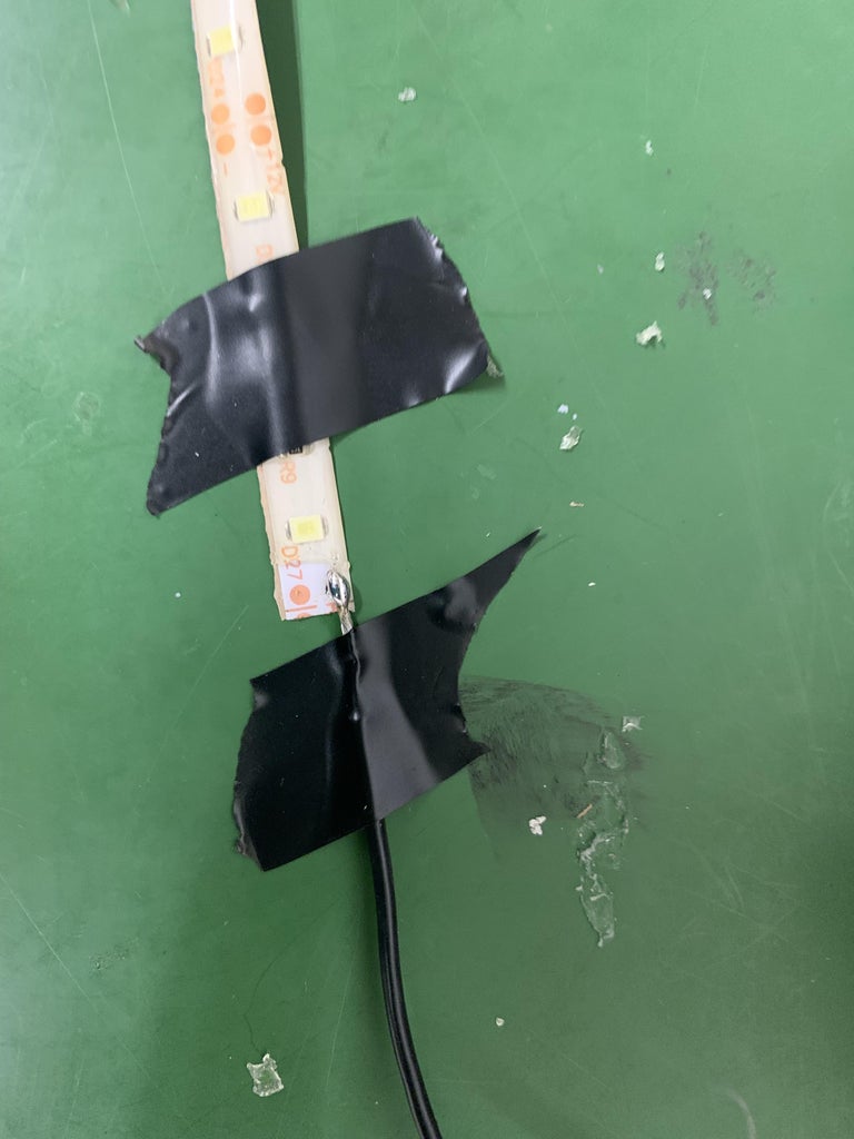
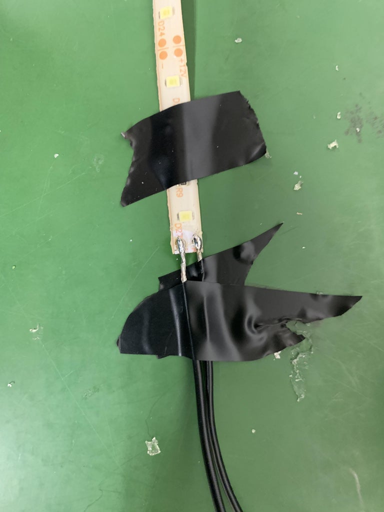
- Solder black wire 5 to the negative connection of the LED and yellow wire 3 to the positive connection of LED strip. To make this easier, use the solder to make small Hershey's-kiss-sized solder droplets on the LED strip at the connection point. Then press the respective wires into the kiss and cover with solder.
- Once attached wrap a small amount of electrical tape around the connection.
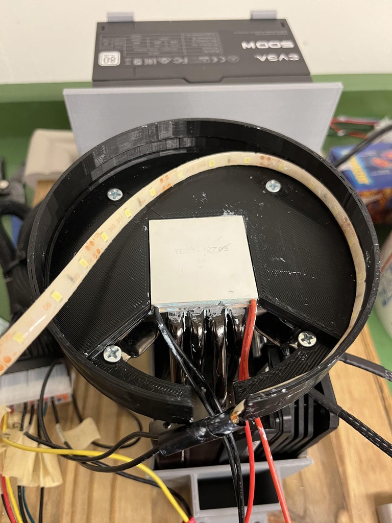
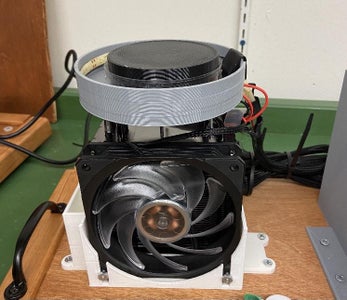
- There is an indentation in the main 3D printed part that's attached to the Hyper 212 cooling fan. Slide the lights into the indentation. To secure the lights add a small amount of super glue to the back of the LED lights then press into the 3D printed part.
- Turn on your cloud chamber to make sure the LEDs turn on
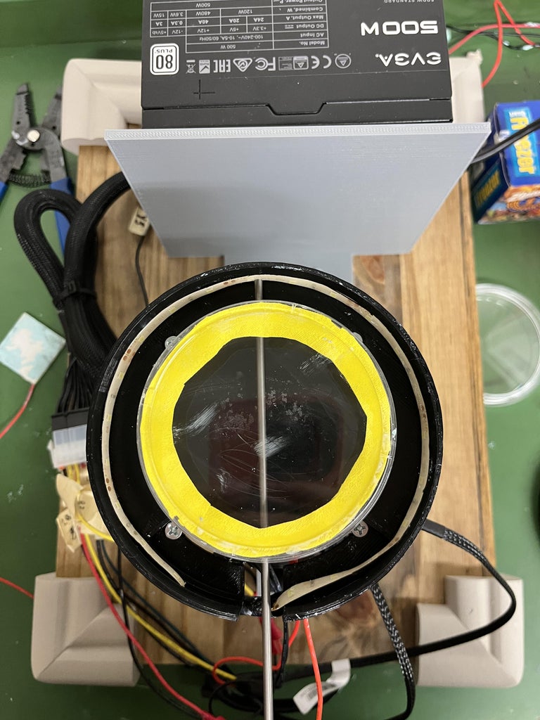
Step 14: Finishing Up
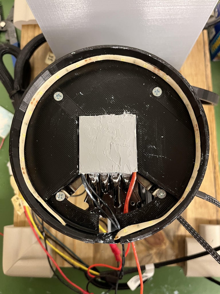
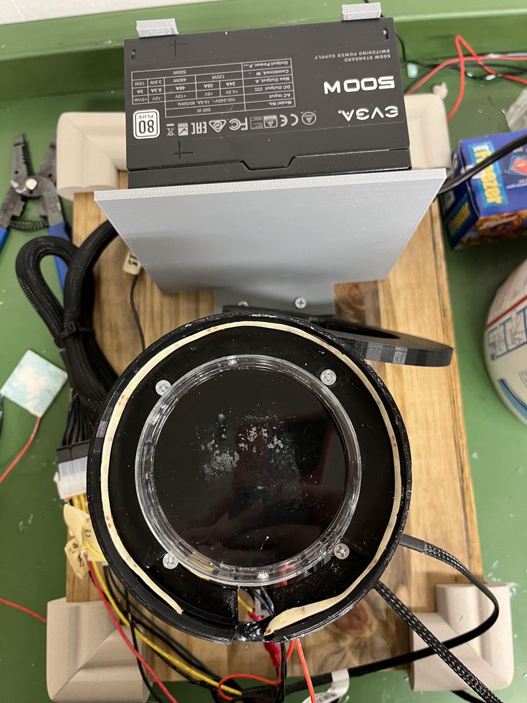
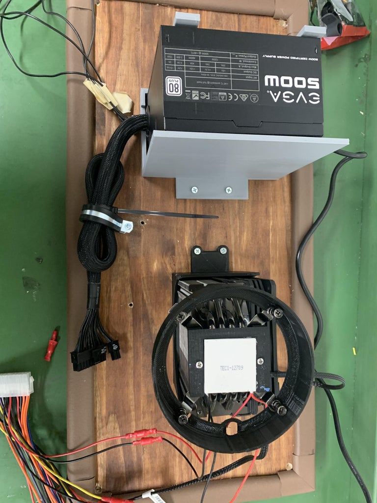
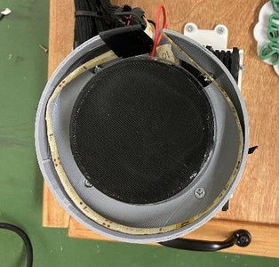
- Put a more generous, but still even layer of thermal paste on top of the 709 peltier and press the black painted part of the petri dish to the top of the peltier
- Place the petri dish with chamois cloth on top of the black petri dish. Use the LED cover to shield your eyes from the LEDs.
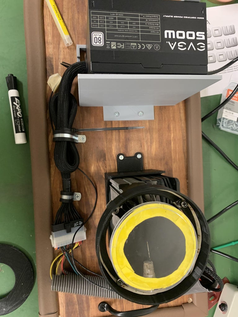
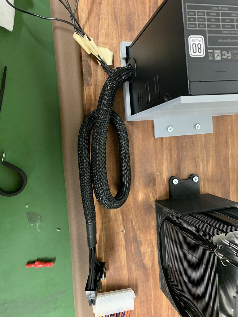
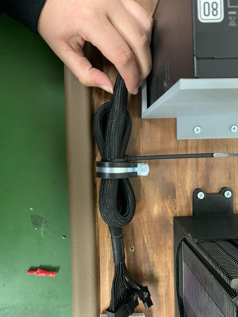
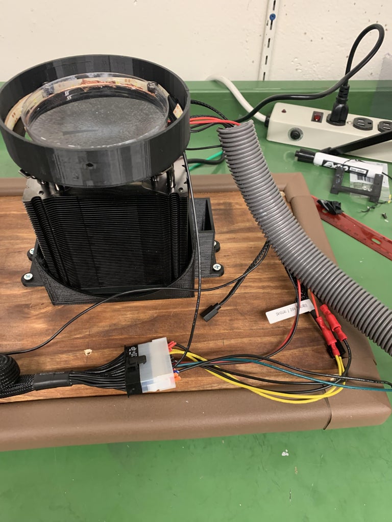
- Take the 24-pin wires from the power supply and fold it like in the picture above. Take a zip tie and tie the wire together. Take the 1" wire clamp and screw it in the hole with the #8 x 3/4 closest to the power supply
- There should be one more hole left to screw in. Take the 1/2" wire clamp and place the wires in the clamp and screw it in with the #8 x 3/4 in screw
- Take the 3/4" tubing. Cut a piece that can cover the wires. (Cut a piece that's a little longer and you can always cut the extra off!). Carefully wrap the tubing around the exposed wires
Step 15: Apply Pressure to Petri Dish Overnight
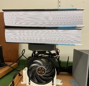
We have found that we get a more consistent connection between the petri dish and Peltiers if we apply pressure overnight. The petri dishes are just thin plastic, so we designed a "puck" that can be placed in the center of the petri dish and then have a weight (we used a couple of heavy books) placed on it. We then leave this overnight.
Warning! When placing the books on, just be careful not to tip things over or you can decouple the petri dish from the Peltiers.
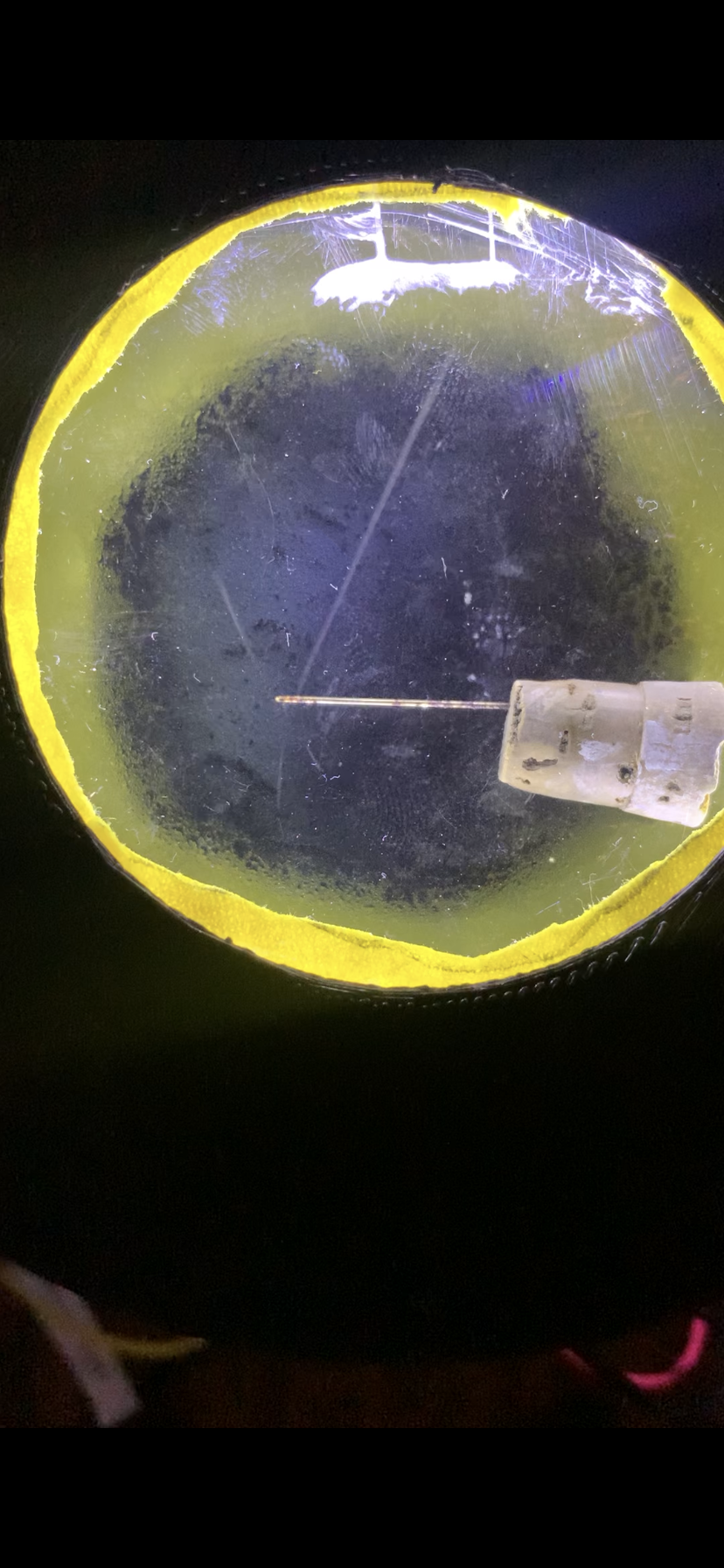
Step 16: Add Your Source
- Take a pipette and add small dots of alcohol onto the chamois cloth
- We have found that about 0.5mL of alcohol works!
- Make sure that you're using 91% or higher purity of alcohol!
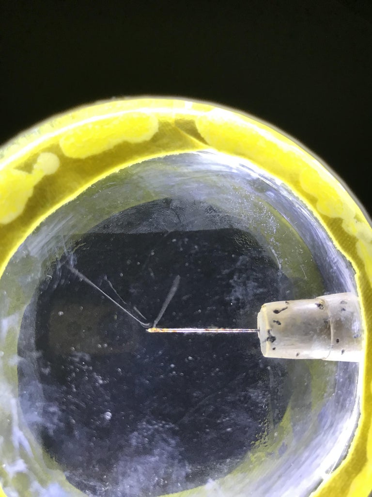
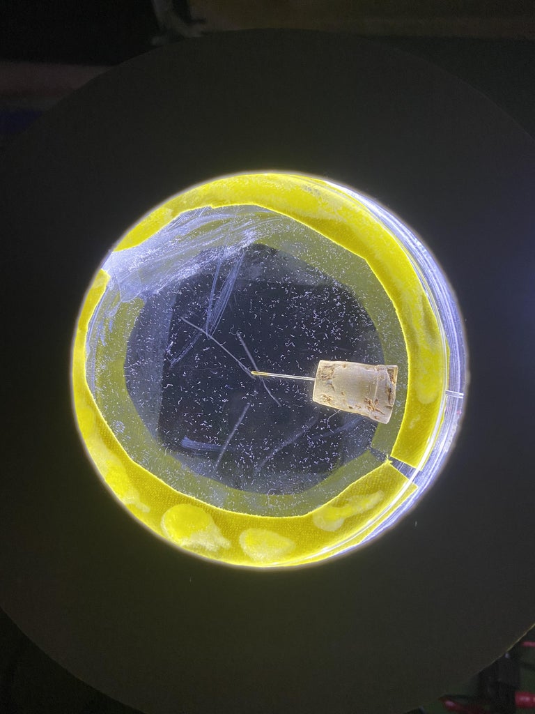
- Place your radioactive source into the petri dish (in the picture is a tungsten welding rod)
- Turn on your cloud chamber!
Congrats, you have finished your cloud chamber particle detector!


9 Comments
5 weeks ago
That are particularly useful for detecting and studying ionizing radiation, such as alpha particles, beta particles, and cosmic rays. By observing the tracks left by the particles in the cloud chamber, scientists can analyze their properties, measure their energies, and study their interactions.
5 weeks ago
An introduction is essential. I cannot afford to waste my time reading an entire instructable if I cannot easily determine its function, attributes and limitations from the beginning.
5 weeks ago
Looks very cool, whatever it does. Strongly recommend that you put an introduction in the front that explains what this is, how it works, and why it's so cool. You are losing most of your audience by starting with a parts list!
Question 5 weeks ago
Very nice. I missed the intro.
What types of particles might users typically use this to detect?
Why might someone use this to detect said particles?
Thanks
Question 6 months ago on Step 14
Thanks for the instructable. What is the cork with the little needle sticking out of it? It seems important for proper operation. Can you describe what it is and how to mount it?
Answer 4 months ago
That is the radioactive source that produces the decays. In the picture is pb-210. But you can use tungsten welding rods to also see active decays. Here is a link to for the welding rods: https://shop.tungsten.com/tig-welding-electrodes-10-pack/?sku=40400-01770B&utm_term=&utm_campaign=*LP+-+Shop+-+Smart+-+All+Products&utm_source=adwords&utm_medium=ppc&hsa_acc=7470597278&hsa_cam=17943107453&hsa_grp=&hsa_ad=&hsa_src=x&hsa_tgt=&hsa_kw=&hsa_mt=&hsa_net=adwords&hsa_ver=3&gclid=Cj0KCQjwlPWgBhDHARIsAH2xdNdyaPNGk2MNGuZYvrVhqS6V8_B6d081CyJQdeU5ahzaDvLZZRCCnnwaAj4wEALw_wcB
Reply 6 weeks ago
Regarding the recommendation to use tungsten welding rods as a source of radioactivity - To be clear it has nothing to do with the tungsten, except that thoriated tungsten welding rods have thorium in them and it's the thorium that is radioactive. A plain tungsten welding rod will do nothing for the cloud chamber, but a thoriated tungsten welding rod is radioactive and should provide some cloud trails.
3 months ago
Thanks for the great instructable. One question: other designs I've seen incorporate a high voltage source (to increase the temperature differential and increase alcohol evaporation I think). Have you found that not to be necessary?
Reply 7 weeks ago
Past designs we have tried using a higher voltage source but didn't see a large difference so we don't find it necessary.