
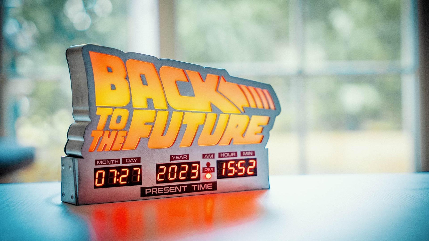
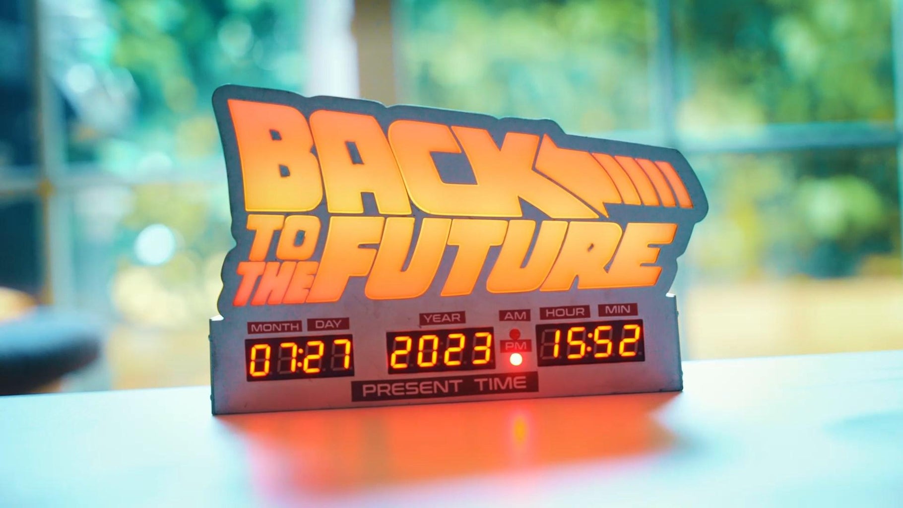
Introduction: Back to the Future Lamp & Clock


Originally, I started from the "high part", the "simple logo lamp". Then I thought: "Shouldn't I add a Back to the Future clock, in the style?" And that's it !
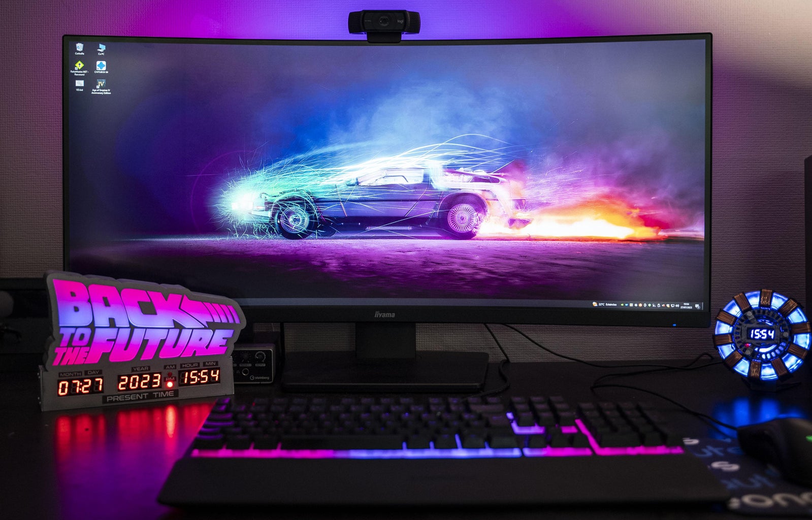
On the back, you'll see a small button, which changes the color, I put three different ones, but you can modify the code and add your favorite color.
Date and time are synchronized via Wi-Fi, don't forget to write your wifi credential in the code.
The components here : https://jeje-linge.fr/pages/bttf-lamp-and-clock
Supplies
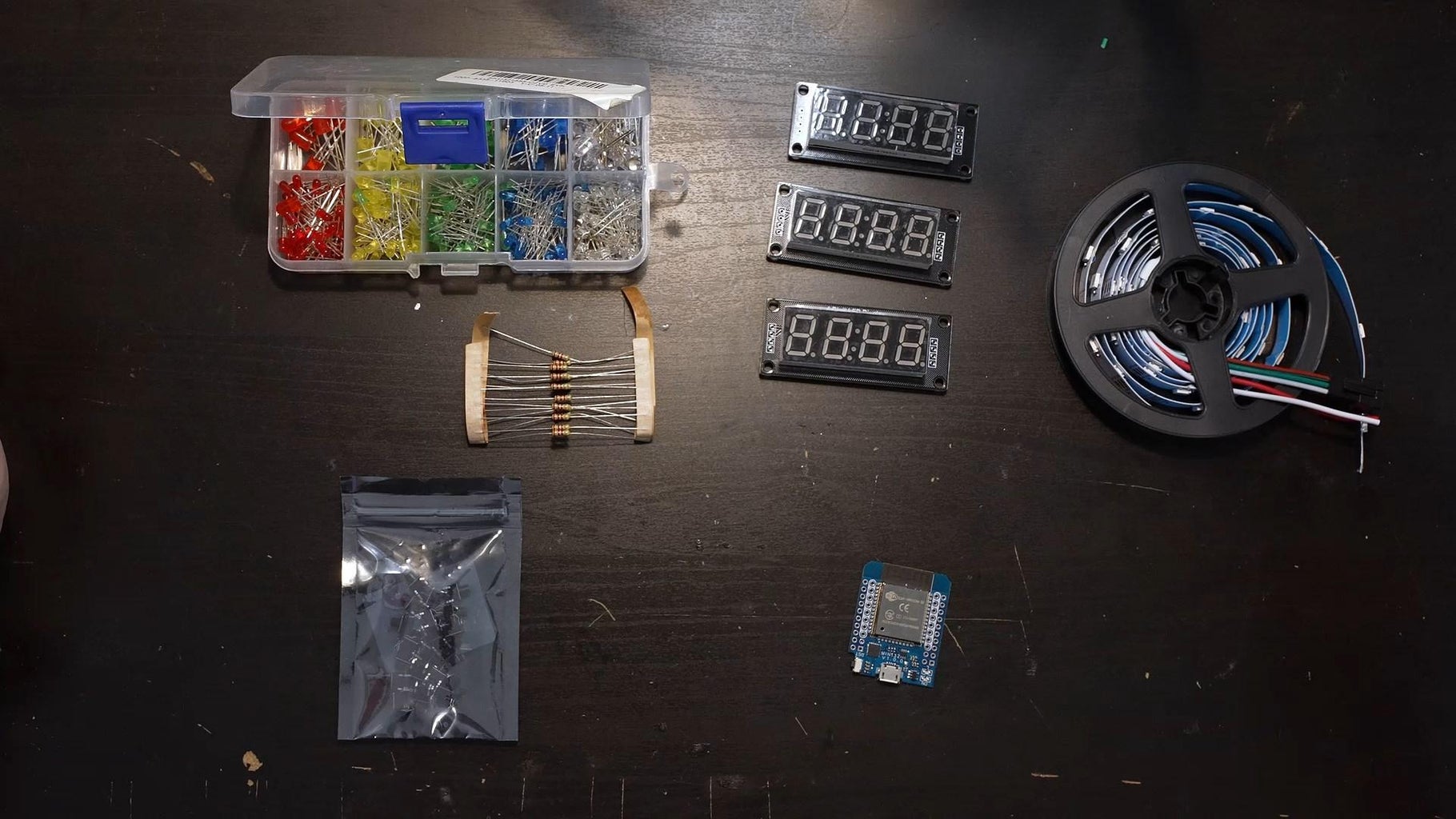
What you need:
- 2x red LEDs
- 3x displays
- 2x 220 Ohms resistors
- 1x 2.2K Ohms resistors
- 1m Led Strip RGB
- 1x Mini Esp32
- 1x Micro switch 6x6
- Wires
My bundle here : https://jeje-linge.fr/pages/bttf-lamp-and-clock
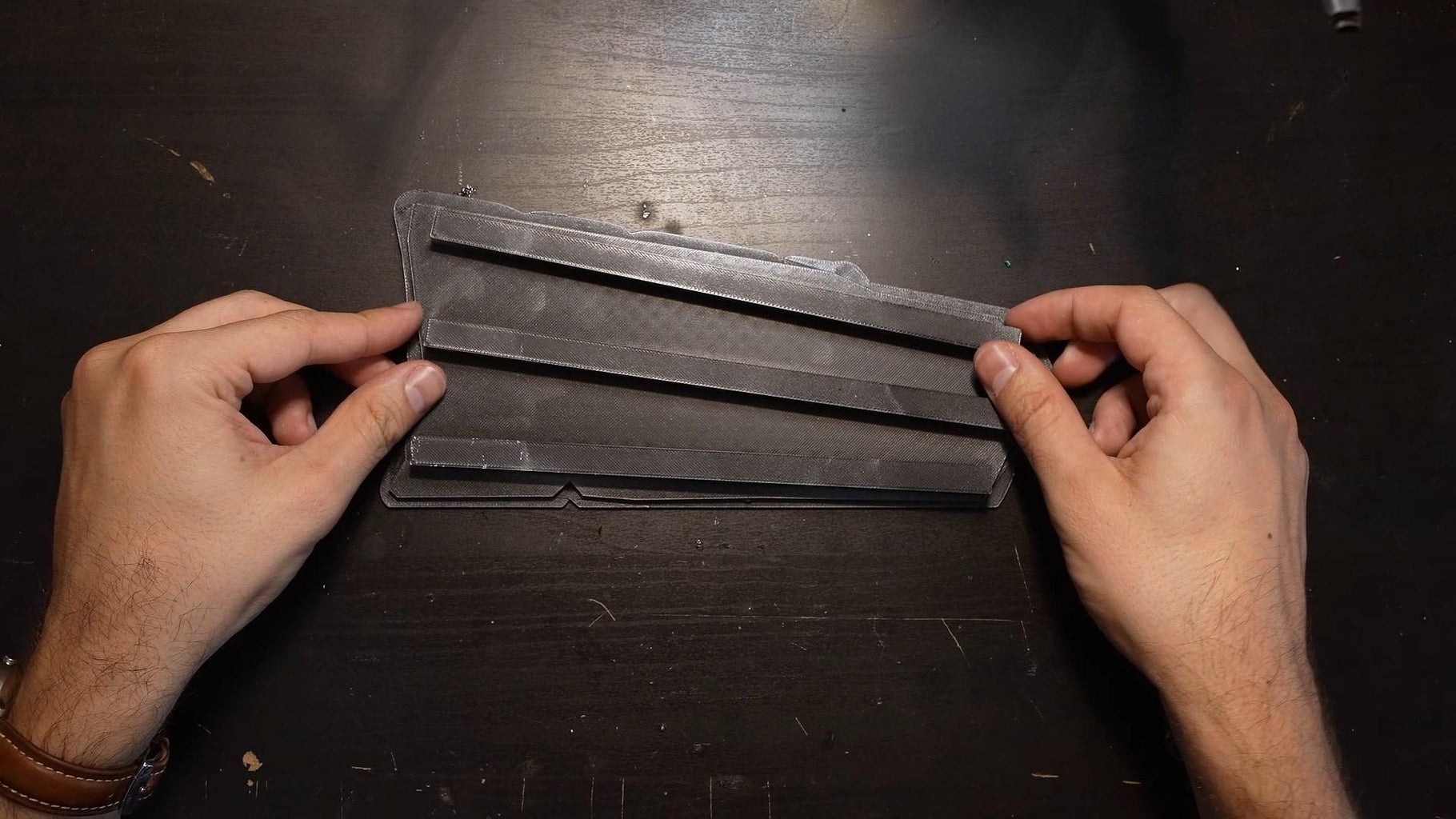
Step 1: Print the Parts
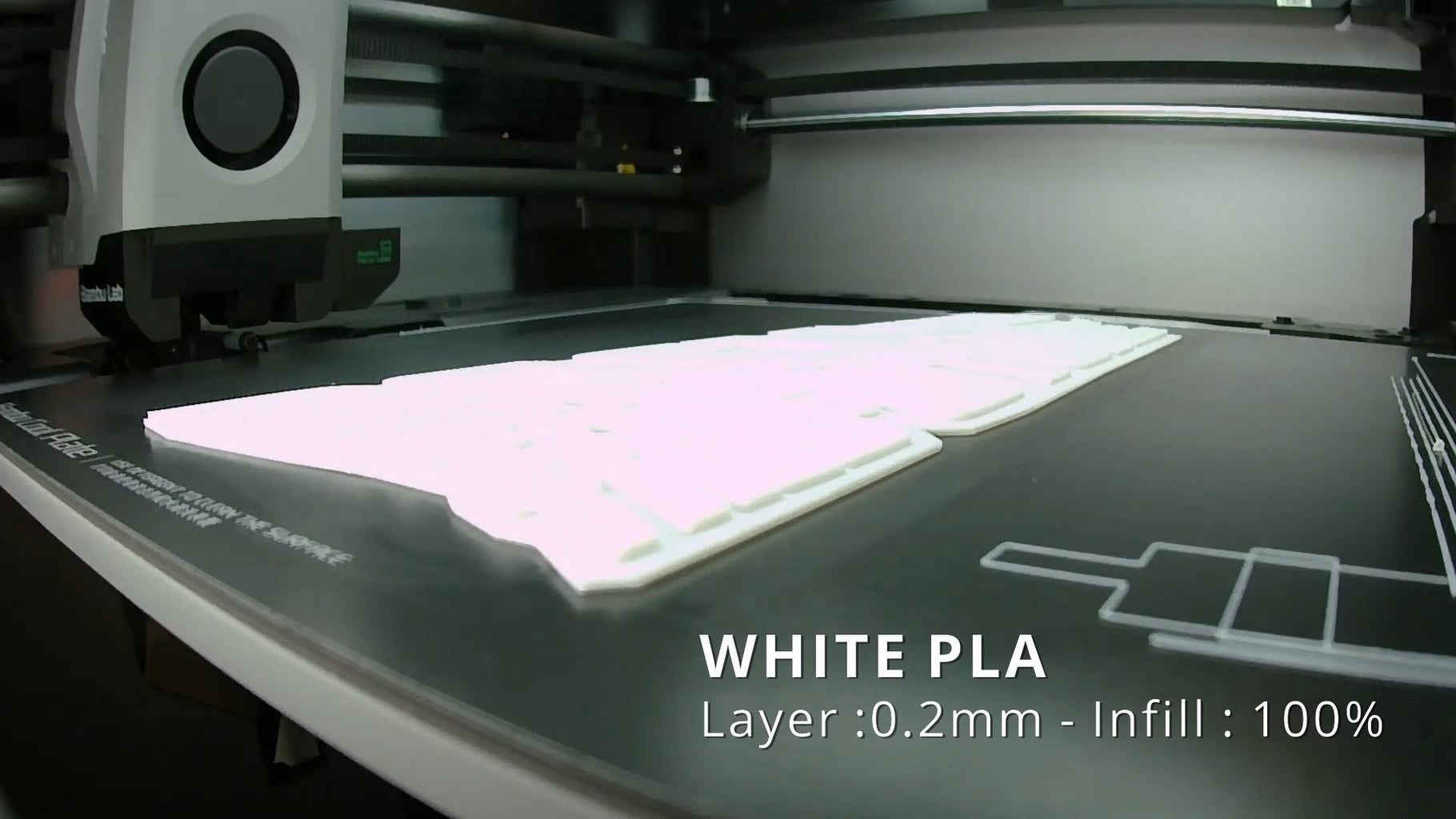
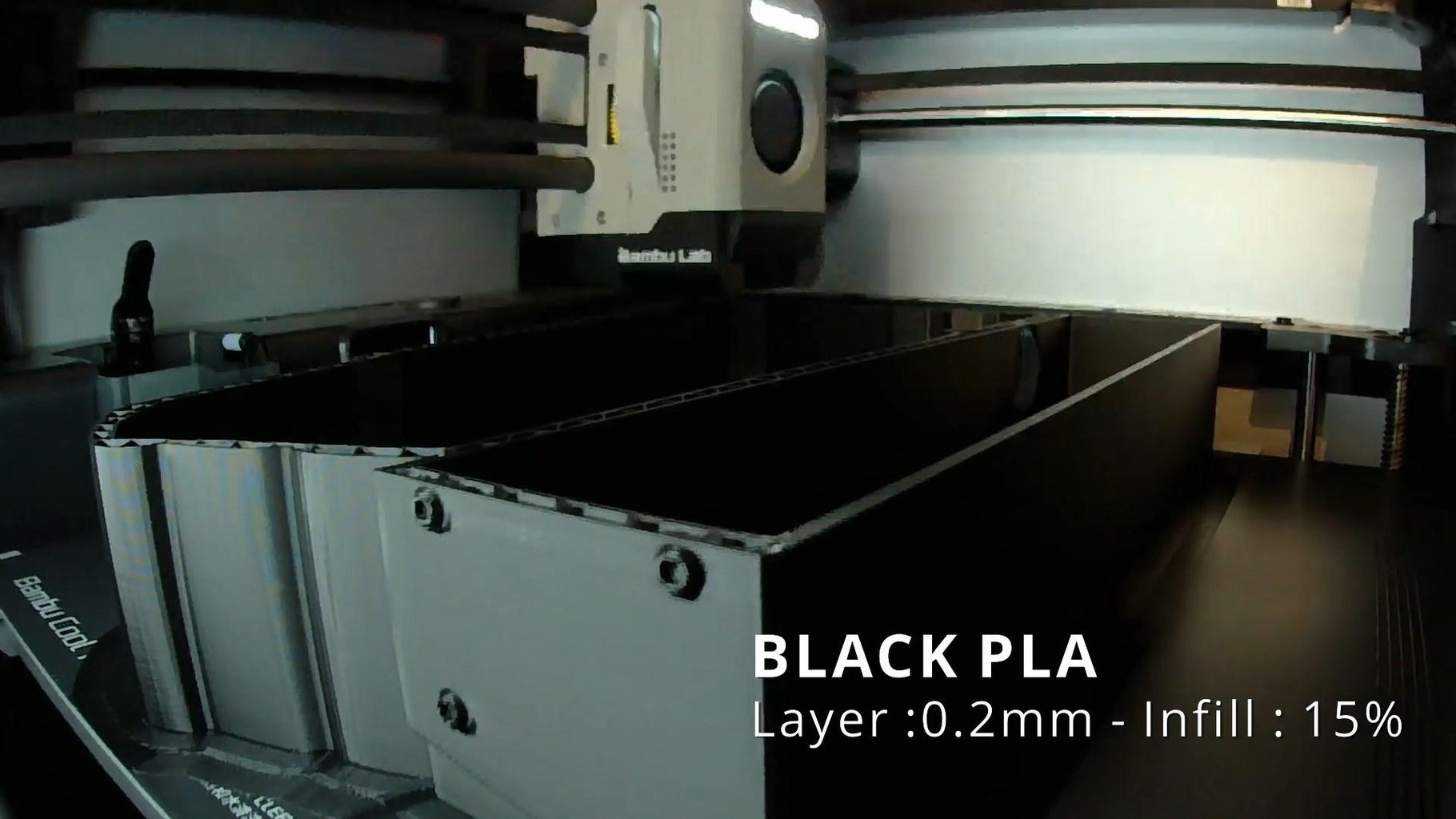
Print every part.
I used black PLA but you can totally make it with grey PLA.
White PLA for the letters.
Layer 0.2mm, infill 15% for everything but the letters.
Letters: layer 0.2mm, infill 100%


Step 2: Painting
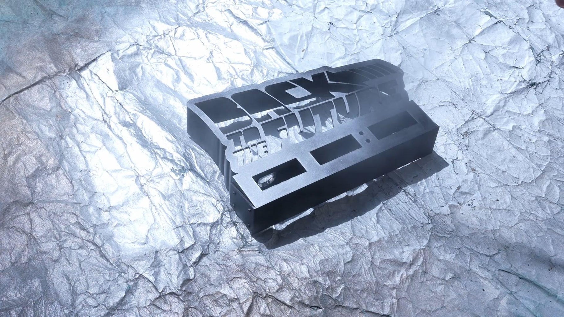

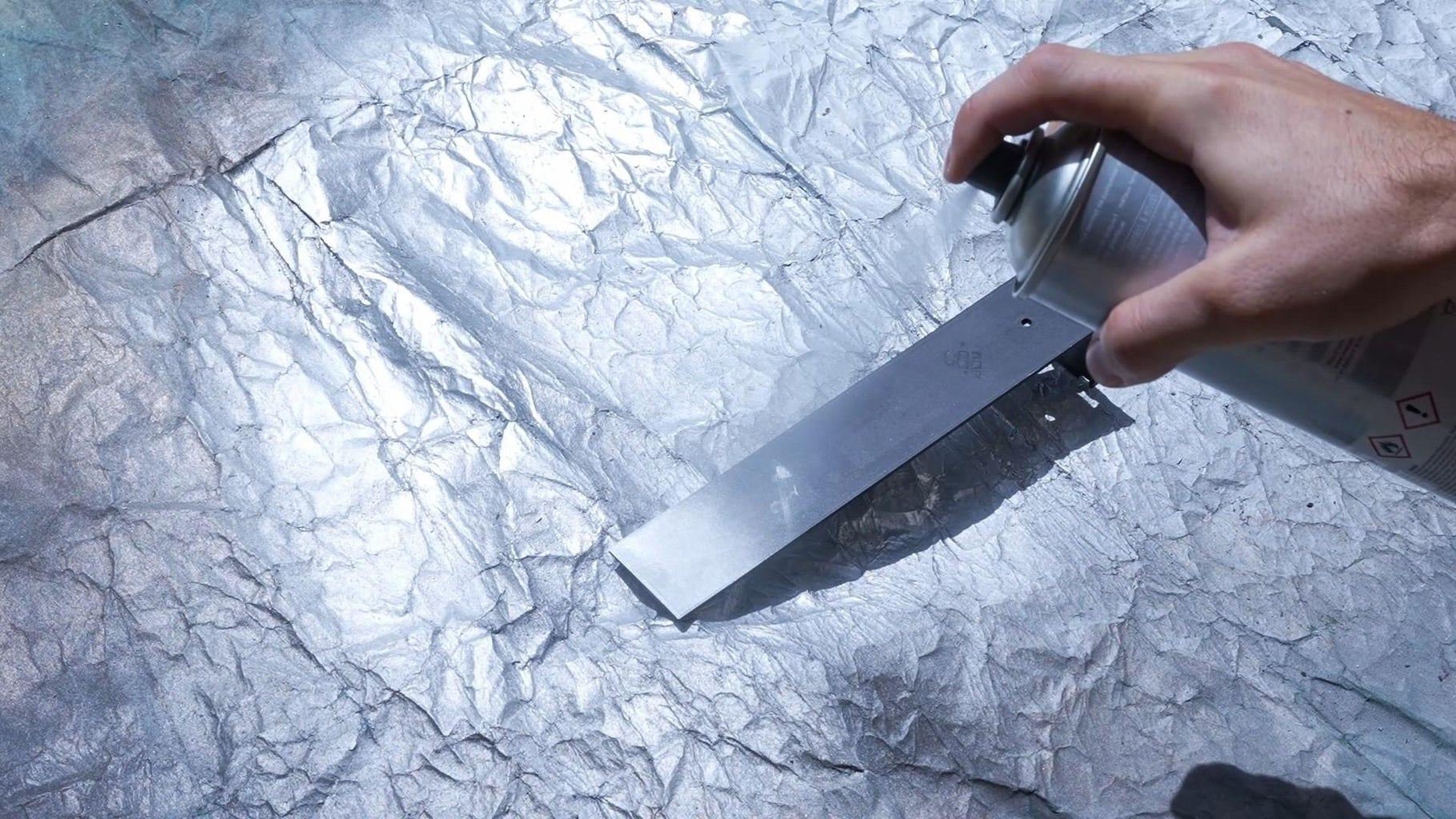
I used metal spray paint.
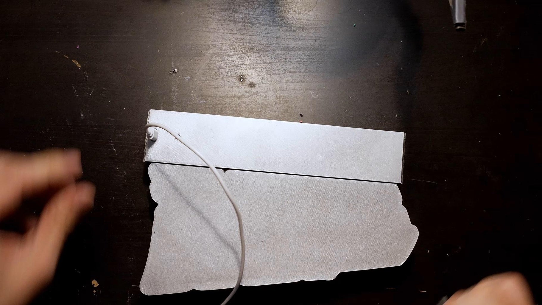
Step 3:
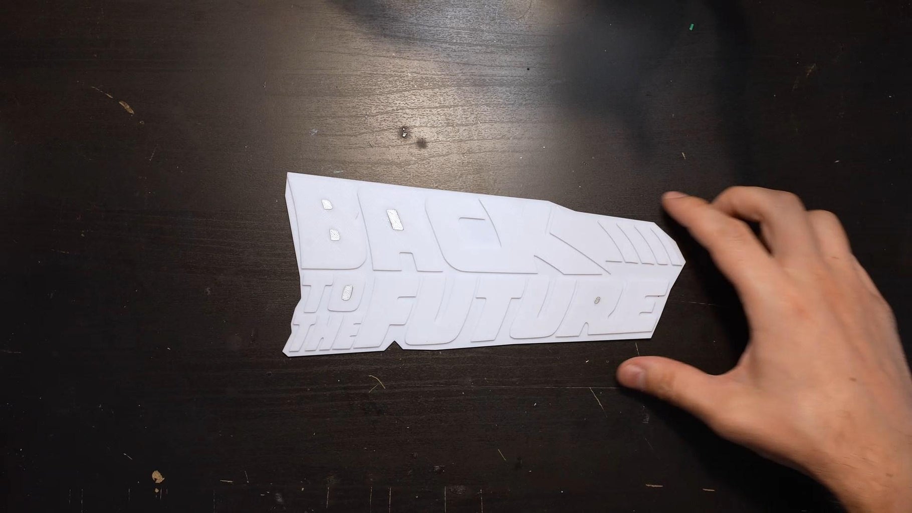
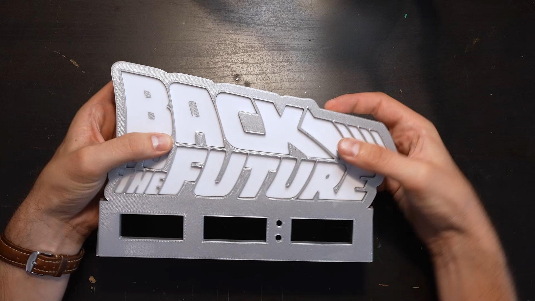
Insert the "caches" in the letters B, A, O and R.
Then place the white plate inside the model.
Step 4: Solder the Leds
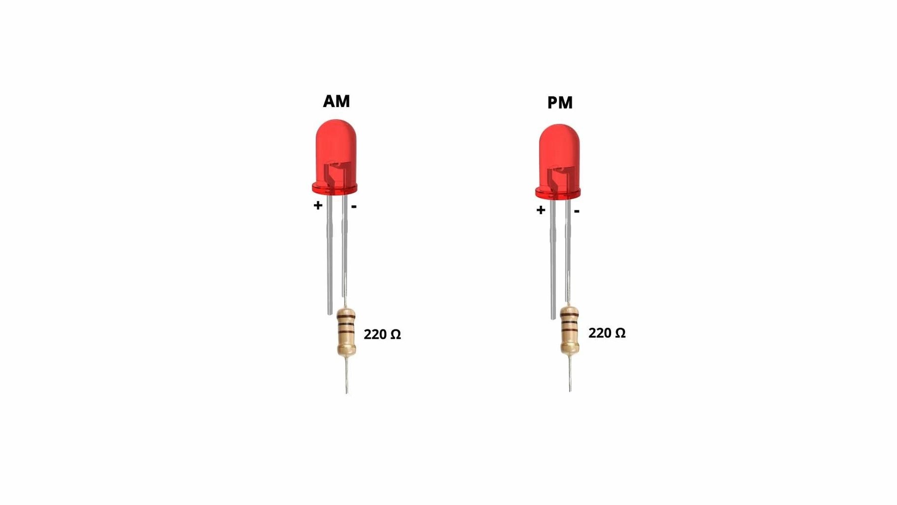
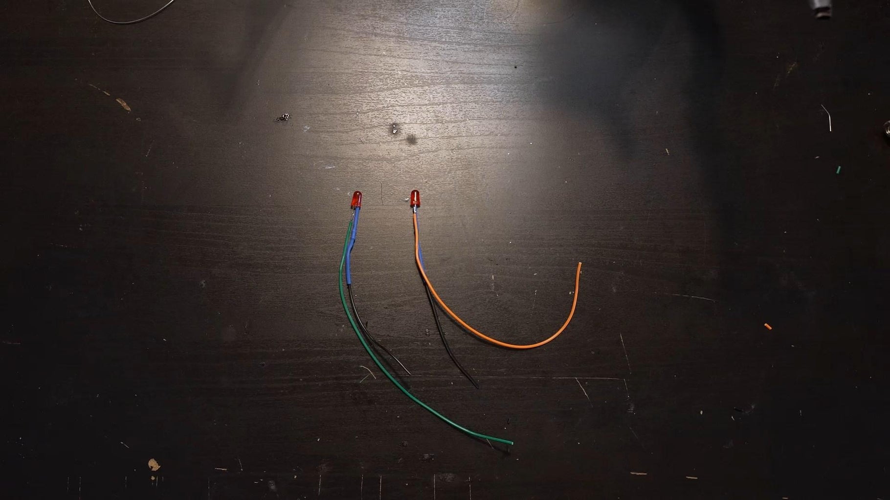
Solder two 220 omhs resistors on the red leds.
Step 5: Glue the Led
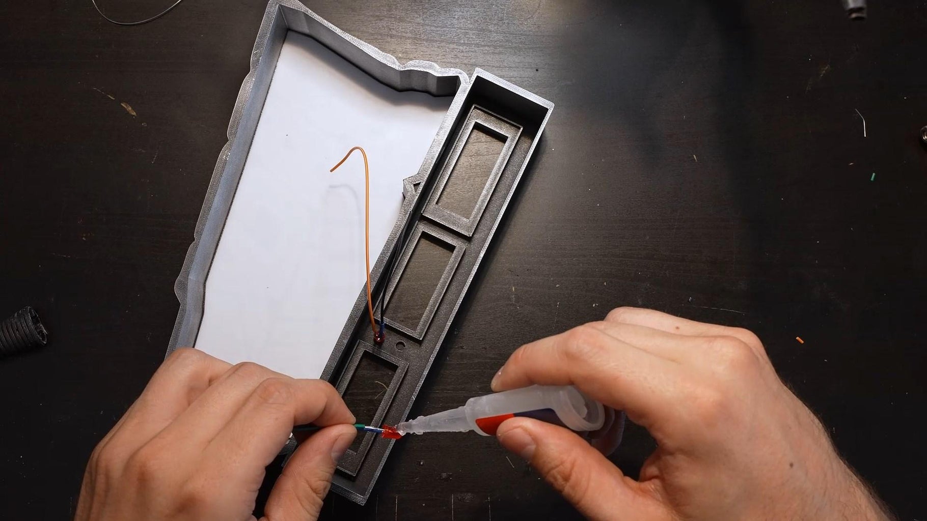
Glue the two leds in the model.
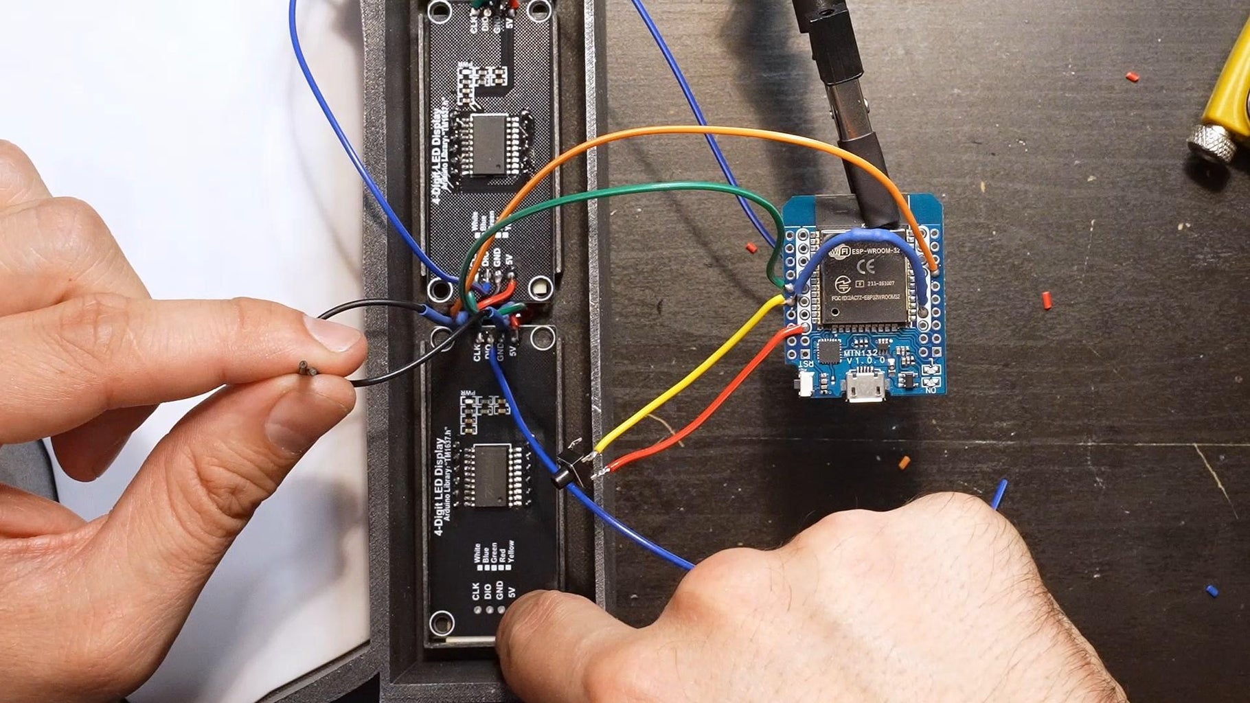
Step 6: Chain the Displays
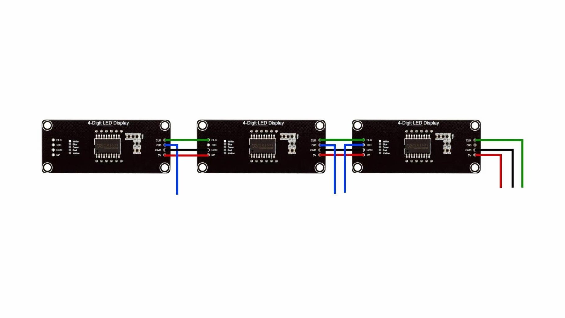
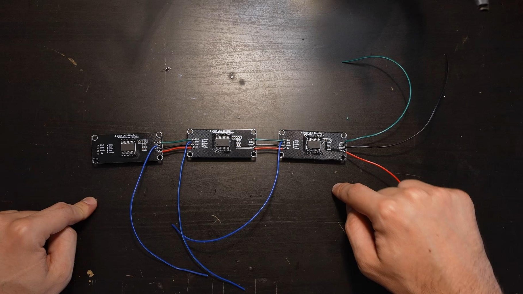
Connect the 5V, GND and CLK of all the displays.
Use 1 wire per DIO input.
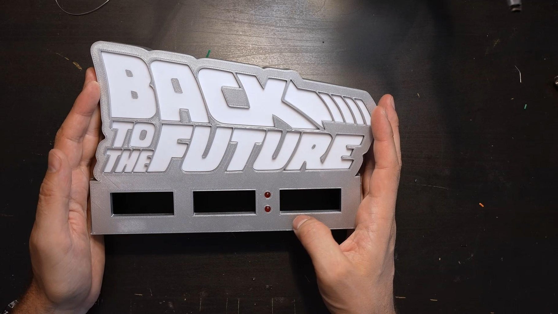
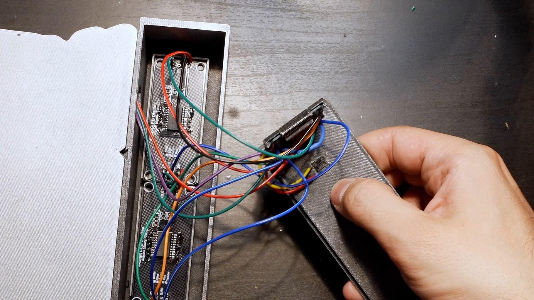
Step 7: Place the Displays
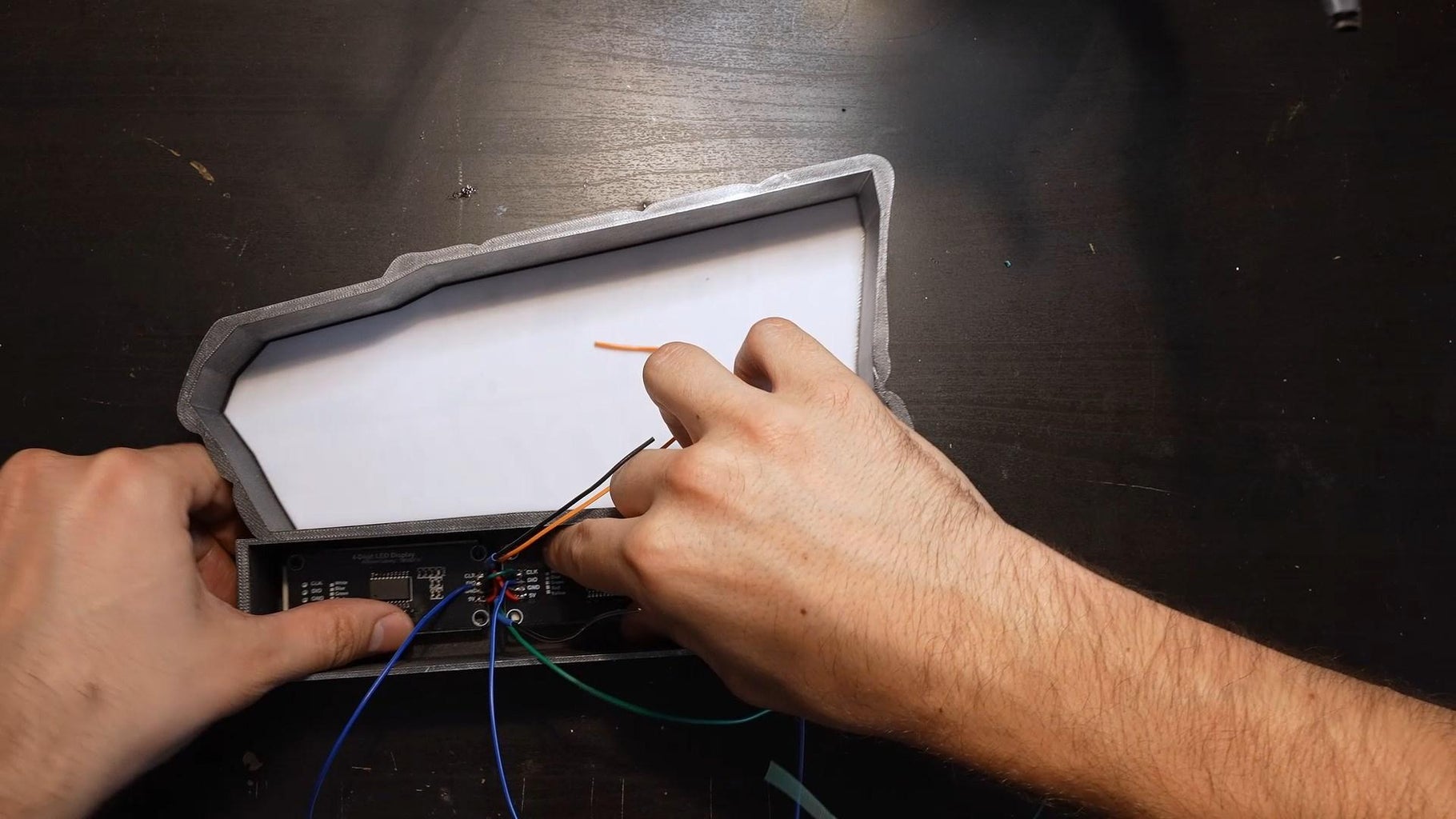
Place the displays in the spaces provided.
Step 8: Glue the Led Strip
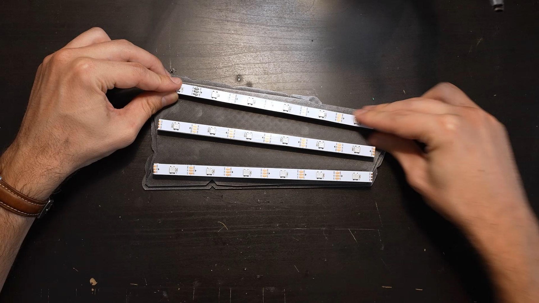
Cut the led strip in 3 parts.
Glue every part.
Step 9: Chain Led Strip Parts
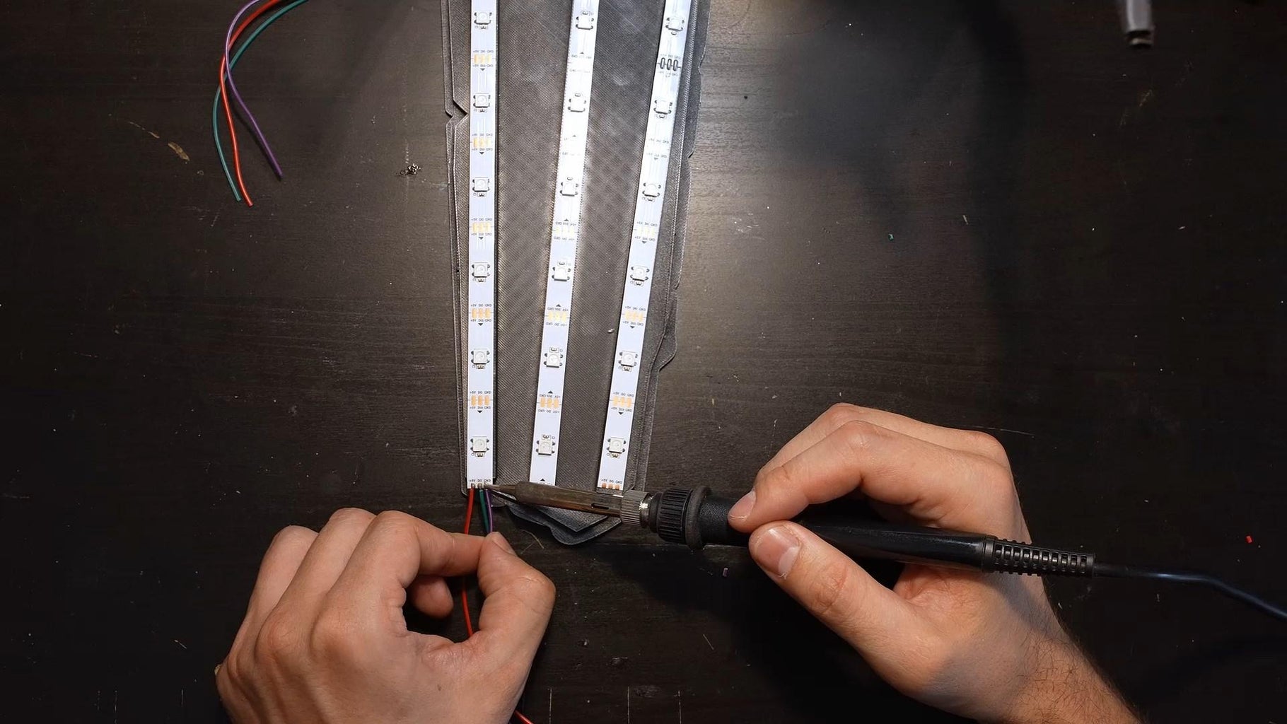
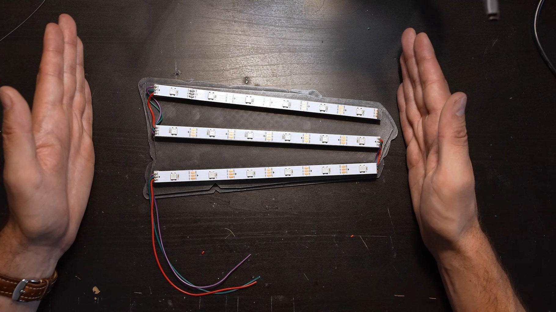
Solder every part together.
Make sure you put the DIN of the first part on the left side.
Step 10: Solder the Switch
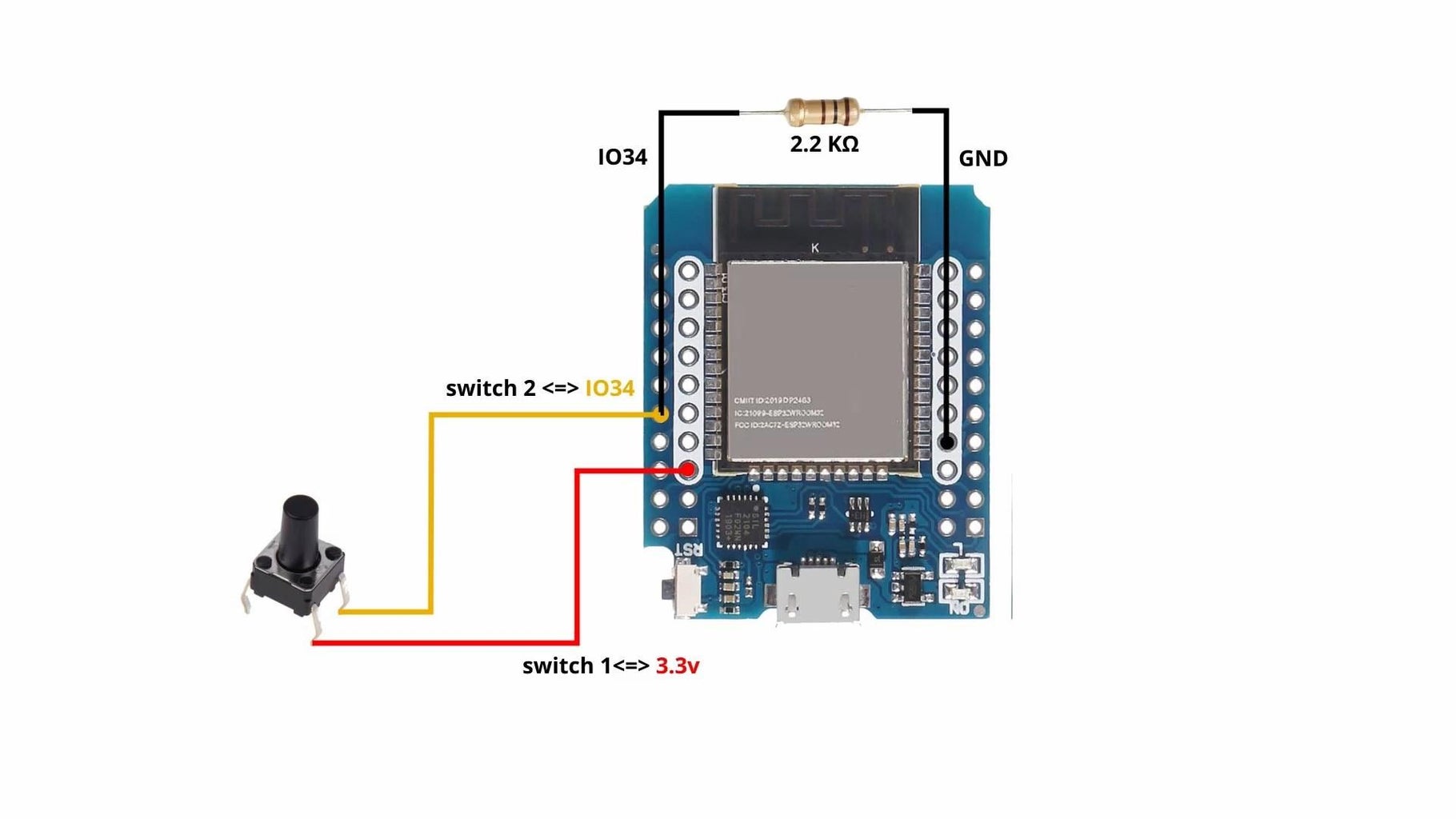
Solder the switch and the "pulldown" resistor.
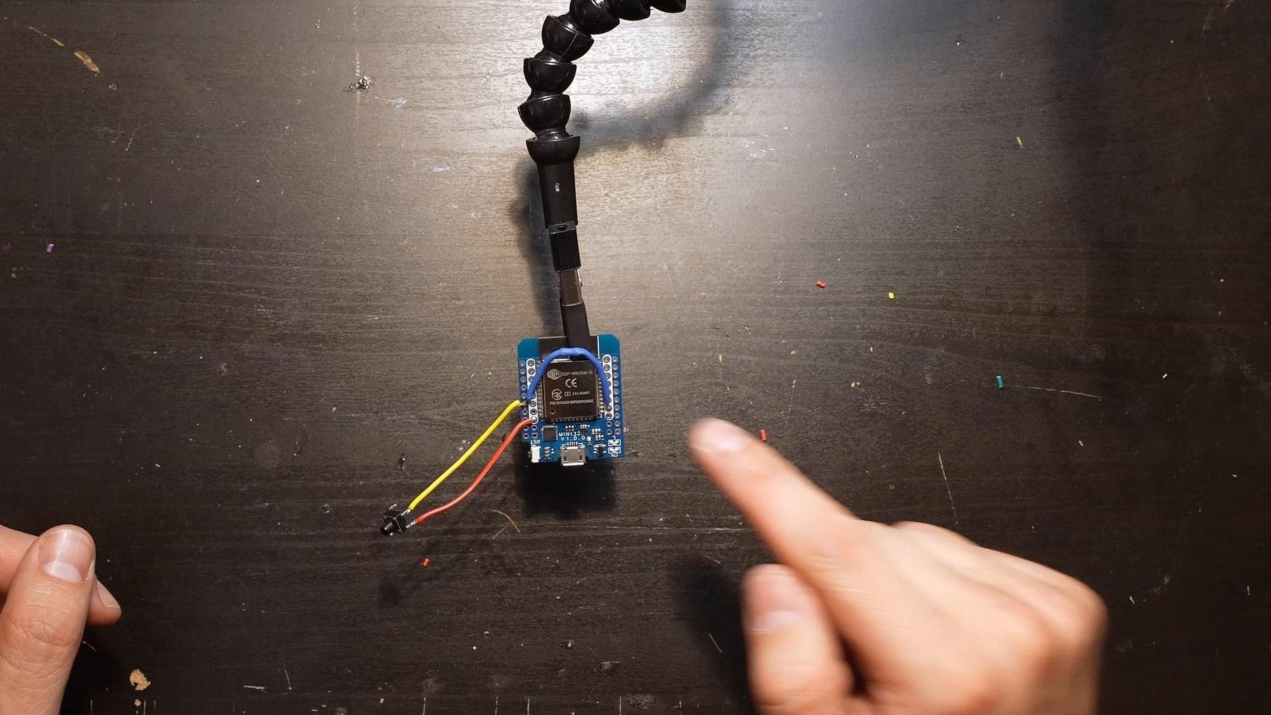
Step 11: Solder AM/PM Led
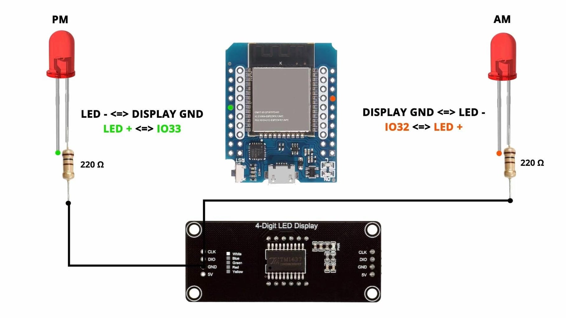
Connect the red led to the ESP32.
The two minus pin must be connected to the GND of the last display.
Step 12: Connect the 5V
Connect the two 5v (led strip and displays) to the ESP32 VCC.
Step 13: Solder the Led Strip
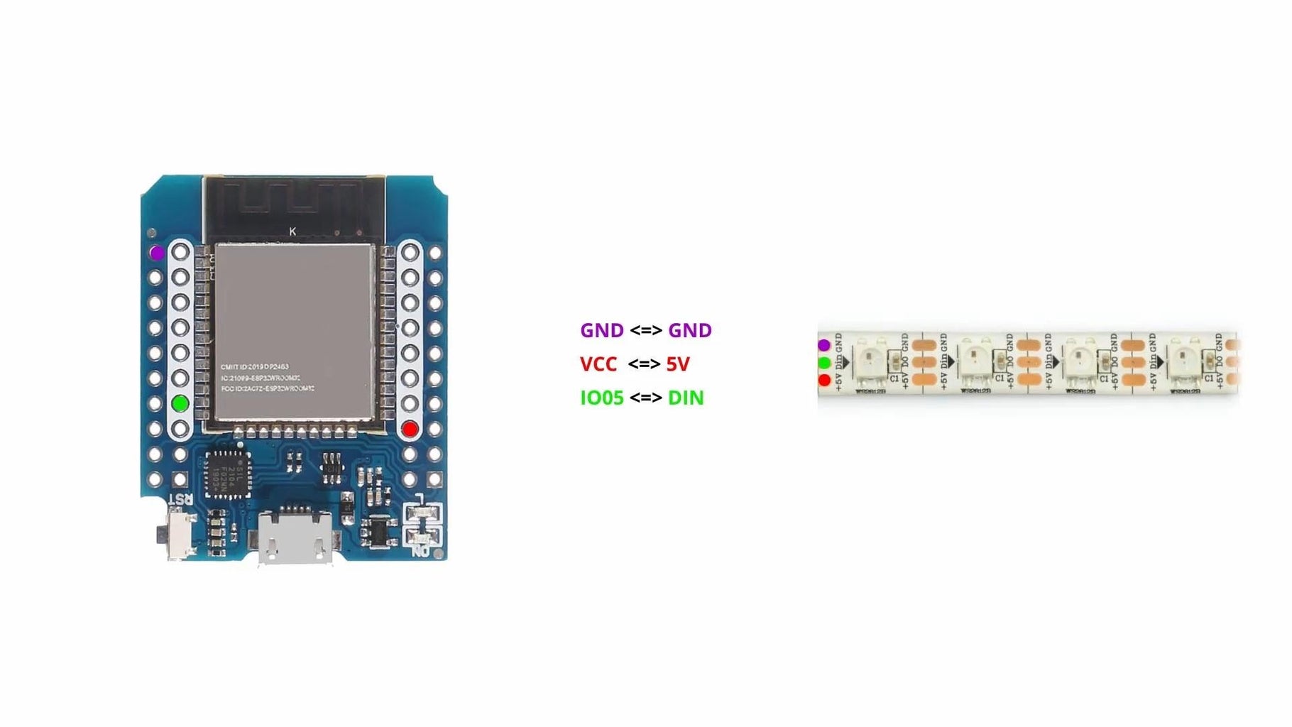
Connect the GND and DIN to the ESP32.
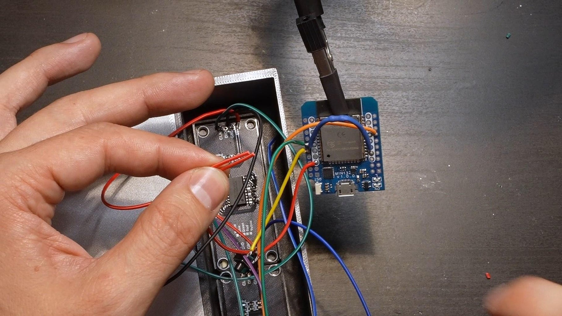
Step 14: Solder the Displays
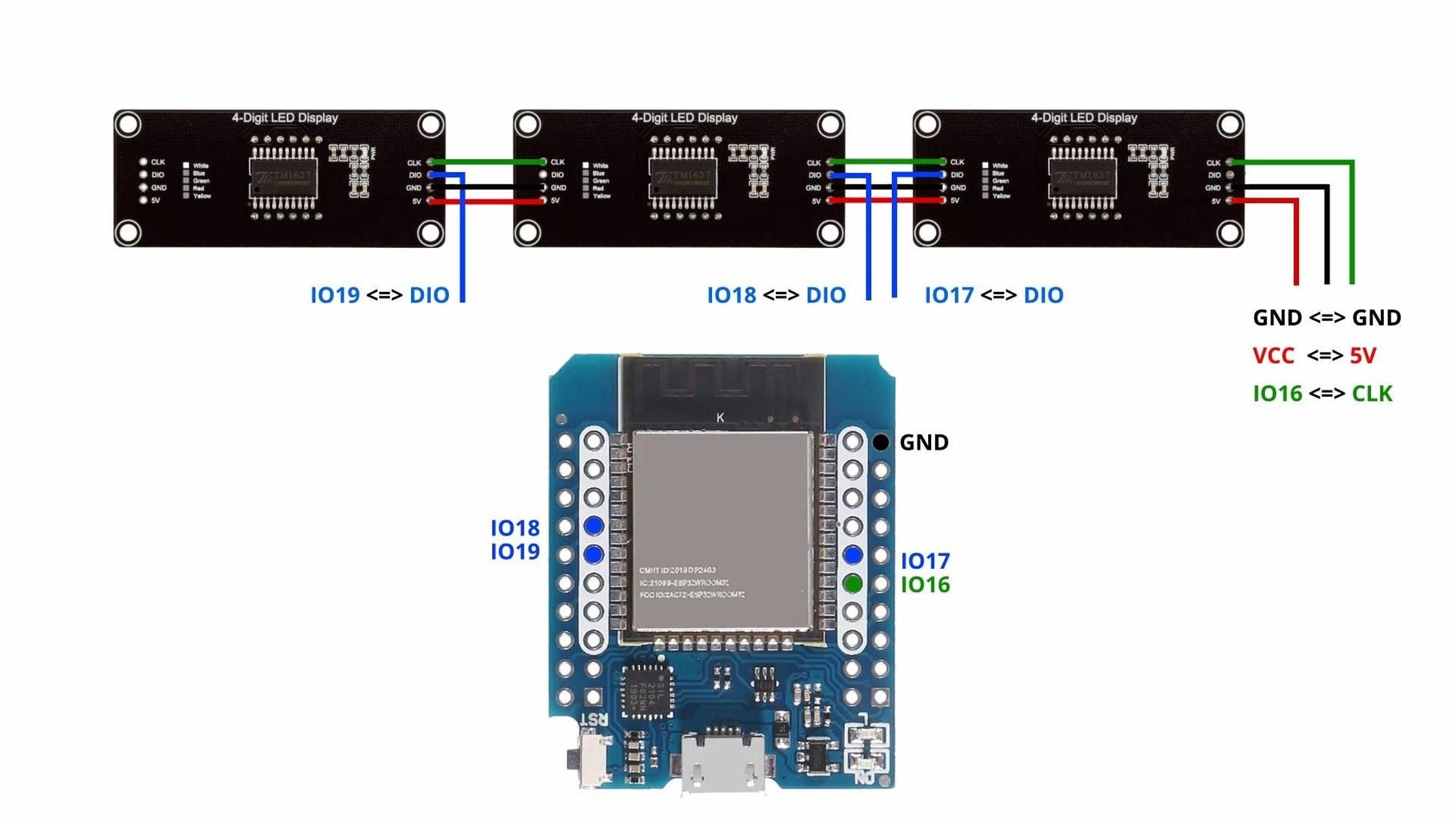
Connect every DIO, the GND and CLK to the ESP32.
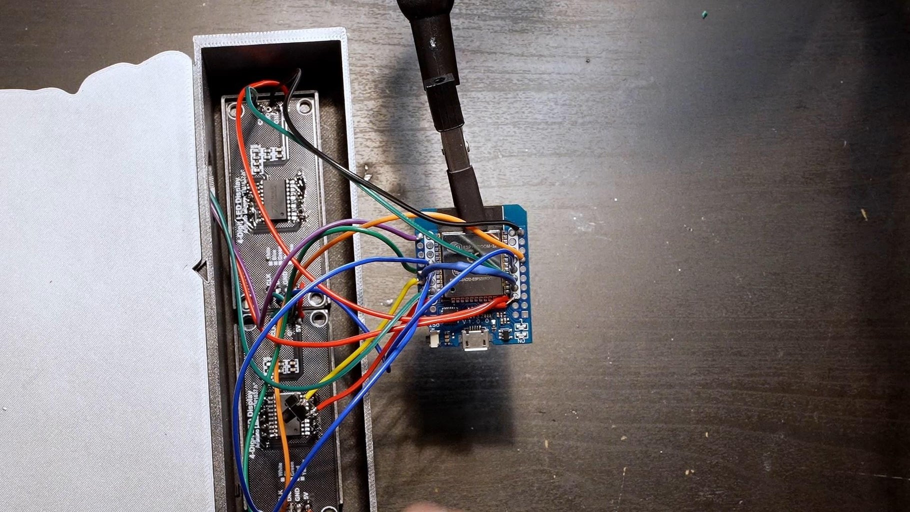
Step 15: Place the ESP32 and Switch
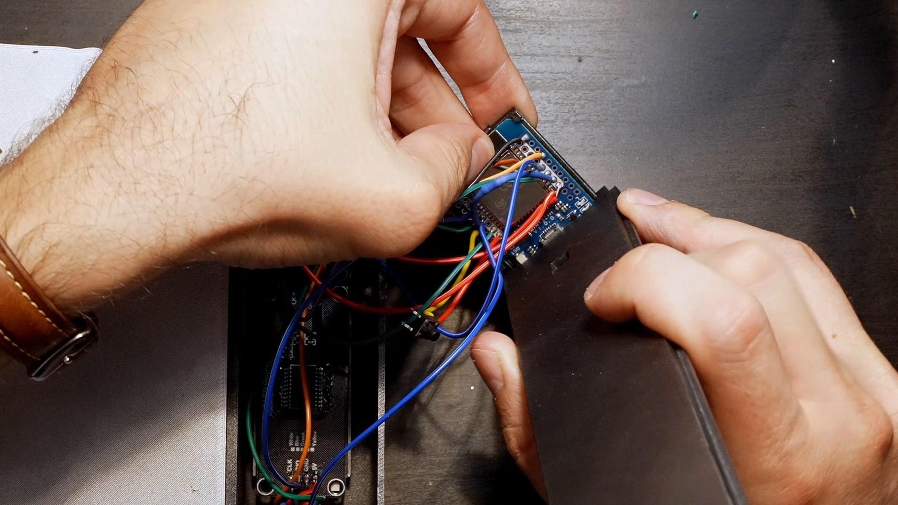
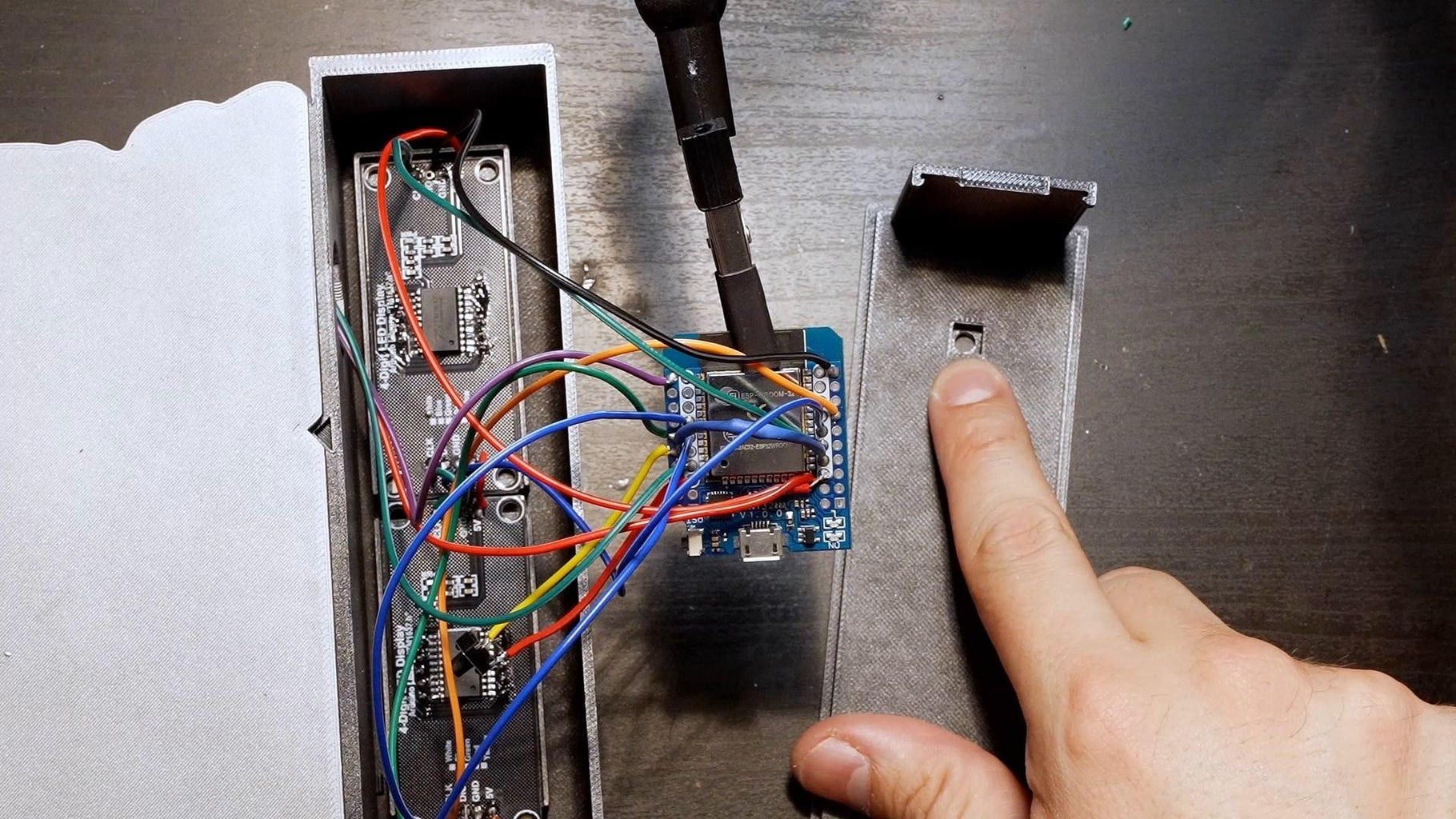
Place the ESP32 and the switch in their places.
Step 16: Stick the Labels
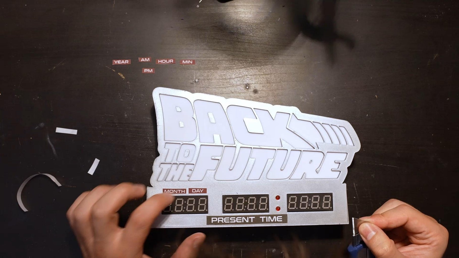
I printed the labels on self-adhesive paper.
Attachments

Step 17: Send the Code
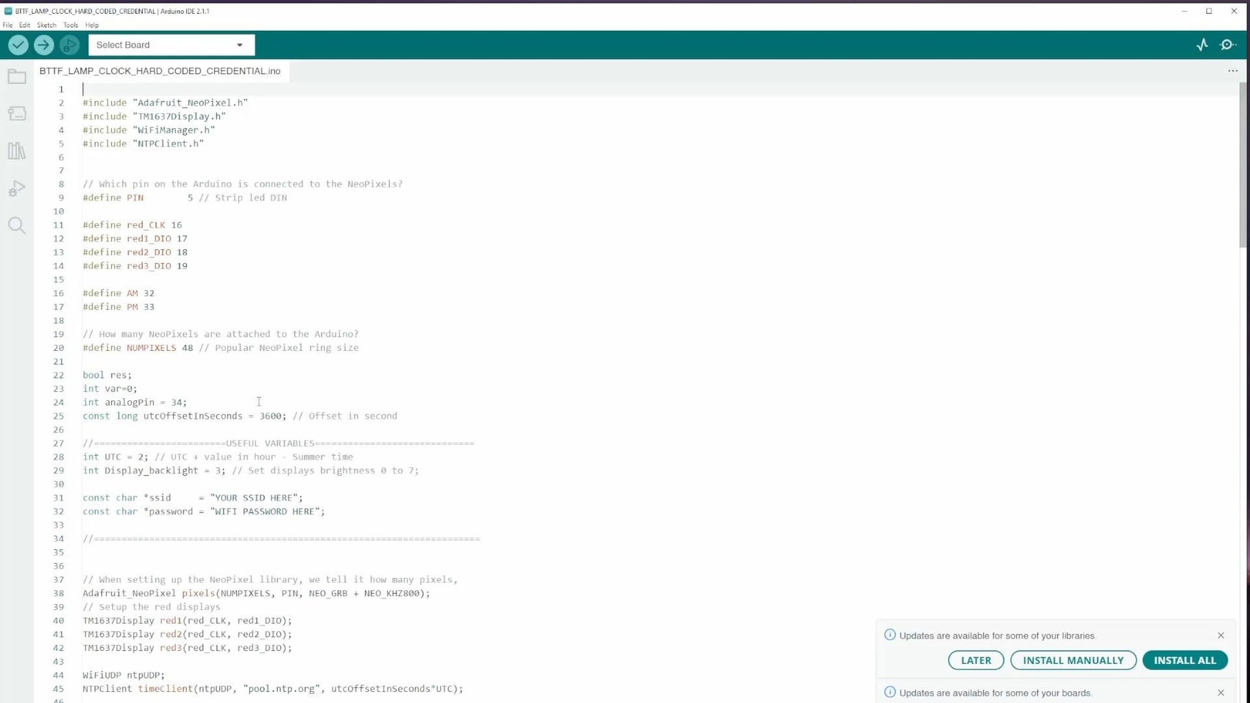
Send the code : https://github.com/jejelinge/BTTF_LAMP_AND_CLOCK
Libraries :
- TM1637 by Avishay orpaz
- Wifimanager by Tablatronix or Tzapu
- Ntpclient By Fabrice Weinberg
- Adafruit NeoPixel by Adafruit
Step 18: Wifi Setup
If you sent : BTTF_LAMP_CLOCK_WEBPORTAL_12H.ino or BTTF_LAMP_CLOCK_WEBPORTAL_24H.ino
Follow the procedure above
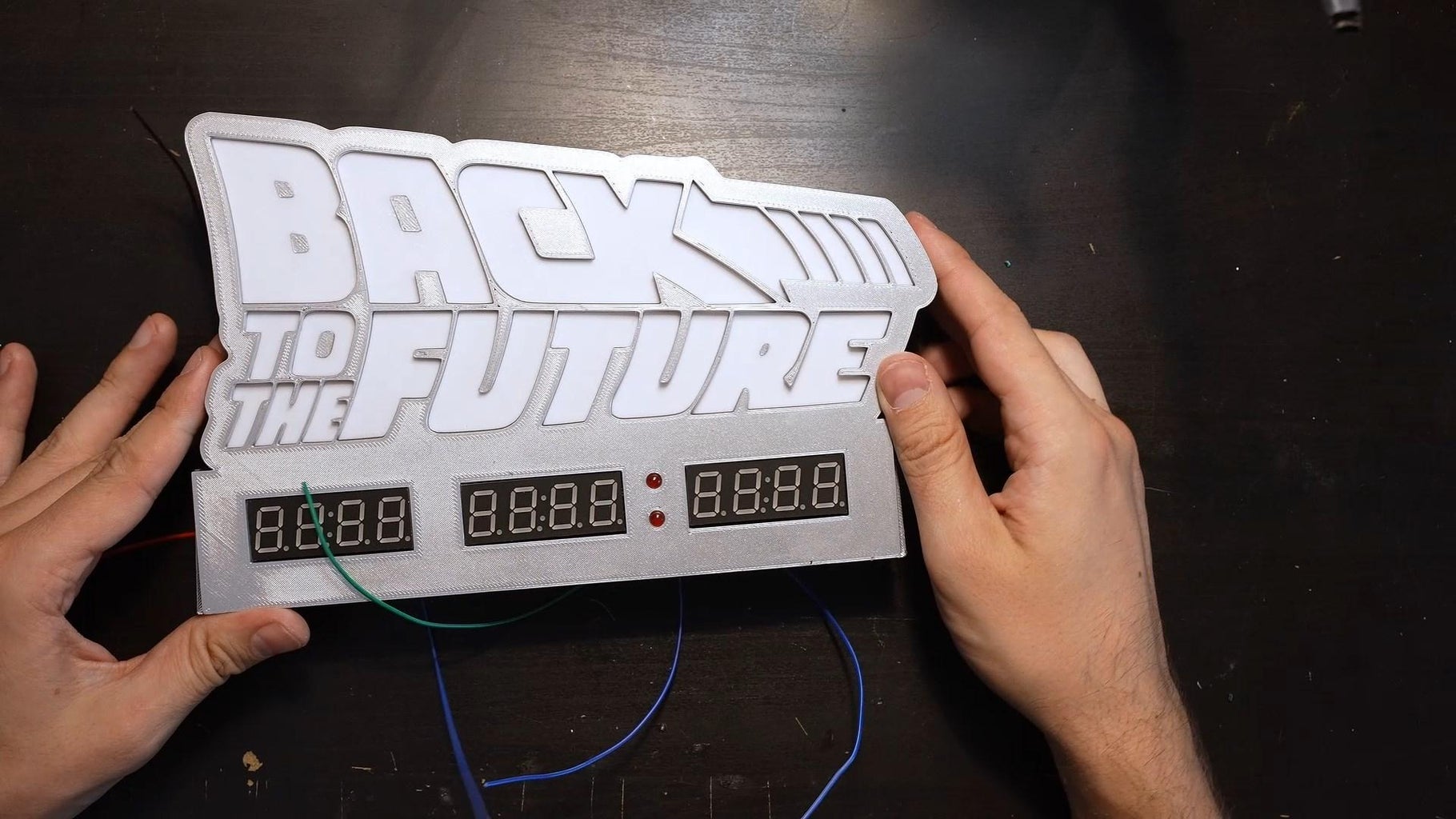
Step 19: Great Scott!
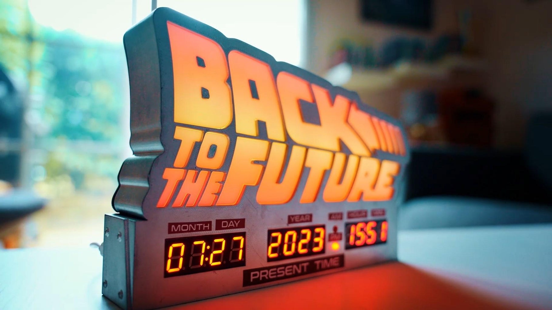

I finally invent something that works!


3 Comments
23 hours ago
WOW!
2 days ago on Step 19
Great Scott!
I'm starting on my build now!
My only suggestion would be another version with three clock rows and the DESTINATION TIME row set to the next minute and the LAST TIME DEPARTED row set to the previous minute.
Thanks for sharing!
3 days ago
Amazing work man.
I'll try to do it but using MDF and thinking about some adjustments for logo contour.
Maybe adding a flux capacitor to it.