Introduction: Ocean City--Assateague Island Seaside Pedestrian Bridge


Hi everyone! Welcome to my project! My name is Anna Zhang, 16 years old, a 10th grader at Thomas S. Wootton High School. I have always been interested in art and design since I was still living in China and entered many competitions and won awards. When I moved to the US two years ago, I started looking for all kinds of architectural opportunities just like before. So when I first came across this website and saw its competitions, I was instantly attracted by people's endless imaginations to make small things into brilliant designs. So I want to also create something that's my own to inspire people. I really hope my little ideas and innovations will open up greater creations for our lives. Thank you for taking time reading this! Let's start.
Supplies
Hardware Materials:
- Hp Windows 10 laptop
- Logitech mouse with a middle button
- Pen and paper
- Foam board
- Acrylic paint
- 50cm ruler
- Hot glue gun
- Glue sticks
- Clear bottled glue
- White foam blocks
- Scissors
- Paint brushes
- Clay
- Micro landscape moss
- Paint brush package
- Tapes with patterns
- Toothpicks
- Straws
- Glitters
- Paper towel
- Thin steel wire
Softwares:
- Fusion 360 educational version:
https://www.autodesk.com/products/fusion-360/free-trial
- Tinkercad: https://www.tinkercad.com/
- Google earth: https://earth.google.com/web/
Step 1: The Detour
This spring, I had a vacation with my family to Ocean City. Before we arrived at the hotel, we decided to visit Assateague Island first because we wanted to see wild horses living on this island. It is an island next to Ocean City, directly to its South. We took the 611 highway and got on the island, then continued heading South, exploring this beautiful island with shallow ooze and wild horses. Driving along the dirt road, it was just slim enough for only a single vehicle to pass through at a time. We had a good time there.

Wild Horses on Assateague Island
Then, it’s time to head to our real destination: Ocean City. However, the GPS navigator was telling us that instead of going along the island North and directly to Ocean City, we needed to backtrack onto 611 highway and take a detour to Ocean City. There was no bridge connecting them! But then, we thought that we were actually lucky because we were in a vehicle. If we walked on the Ocean City jetty first and found out that there was no way to get on Assateague Island that's just less than one kilometer away in front of your sight, that would be very disappointing.

Vehicle Route & Location Map
Therefore, an idea spurted in my mind. What if we can build a pedestrian bridge connecting two islands? Since there is a boardwalk that goes across the entire Ocean City island, people can access the Southern Ocean City jetty very easily. There are a lot of people wandering along the boardwalk and on the beach every day so they can see the bridge and wonder what’s on the other side. Assateague Island is also famous for its wild horses so it became a tourist attraction to people. The bridge will help increase the number of visitors to this national scenic spot and promote the beauty of wildlife and the environment. Plus, there are always going to be people like me who just want to go on the island to experience the fresh air and see the horses themselves. Additionally, this bridge can also reduce carbon emissions from vehicles because it reduces 20 minutes driving time. So this bridge can provide convenience to civilians and tourists, help protect the environment, promote deeper relationship between human and nature and is also easily accessable to all user groups.

Ocean city boardwalk
Step 2: Location
Where should the bridge be constructed exactly?
Hypothesis 1:
The idea is to provide a pedestrian transitional structure between Ocean City and Assateague Island. At first, I thought it would be fantastic if we built a bridge straight across Ocean City jetty (the part below) and Assateague Island jetty (the part above). Because it’s the shortest and the most direct way to connect two sides, it will save a lot of money due to its small span and simple design.

Hypothesis 1 Schematic Diagram
However, this hypothesis might not be the most ideal. According to Google Earth sea depth map, Assateague Island’s jetty’s average altitude is 2 meters and 1 meter at its lowest. Then, if we take the tide chart on 5/25/2023 as an example, the date shows that the high tide of that occurs at 3.9 feet, which is equivalent to 1.19 meters. This could be high enough to submerge most of the outer part of the jetty, leaving a space too slim for people to walk on. At higher tides, it could even submerge the entire jetty. (data shown below)

Assateague Island tide chart 5.25.2023
Hypothesis 2:
The second plan is to build a bridge from the speedboat tier from the West side of the Ocean City to the mainland of Assateague Island. It is a longer bridge, but it solves the jetty submerge problem very well. However, there is no pedestrian path built from the Ocean City beach or the boardwalk to the start of the bridge. The only way is to walk along the edge of vehicle paths through the sand. Furthermore, the tier needs a possible artificial landfill to raise up the starting height. This will cost a lot of human resources and will damage the ocean environment.

Hypothesis 2 Schematic Diagram
Hypothesis 3:
My final plan would be to build a bridge utilizing the jetty as the base to go along with.

Hypothesis 3 Schematic Diagram
Instead of a straight bridge, it will curve. The jetty provides natural support for the bridge so it reduces the time it takes to empty out the surrounding water for the pillars to drill in and also prevents harming sea creatures. It increases the aesthetic of the structure and resembles the flow of sea waves. Although it will certainly be more expensive, it cleverly utilizes the jetty shape, providing the tourists with a path reaching directly to the main beach on Assateague Island.
Step 3: Design
It’s time to design the bridge. Ocean City and Assateague Island are both seaside islands. You can see the ocean next to you when you walk on the islands. The sea waves fluctuate up and down, creating pleasing lines. So I came up with an idea to split up the bridge and the two parts will twist and turn and cross above each other. Also, I chose ramp instead of stairs so disabled people can get on the bridge easily

Pedestrian Bridge Pencil Sketch
Then, I worked on the columns. I designed multiple ones, but eventually chose the simplest one. This column has a stronger support and its spiral pattern also blends with the flow of the platform well so it won’t be too incongruous. Its simplicity can make the bridge pop more. Also, it will go up and down so separated columns will be the best choice for the construction difficulty and load-bearing capacity.

Column Designs

Final Decision
I also designed a scent diffuser and sensor to prevent wild horses from crossing the bridge. The sensor detects nearby horses and sends signals to the administrators. The scent could be citronella oil because it repels horses but is also safe for them. It smells very fresh and lemony to humans so it won’t be too distinctive to us. The model will be shown in "prototype" step.
Step 4: Structure
Now, I need to specify the dimensions of the bridge components.
Bridge Floor Cross Section Sketch
I designed the bridge floor cross section. It consists of two supporting structures, a thin top layer of the floor, two handrails, and LED light tubes along the side of the whole bridge.

Bridge Floor Dimensions
Column sketch
I specified the dimensions for the columns as below.

Column Dimensions
Bridge Body Dimensions
Since this bridge is based on a map that is 1 to 100, I traced an arch based on the map showing how the bridge is curving. Then I calculated the length of the arch using the angle of the arch and the circumference formula. I distributed the arch into several sections. Although it’s not entirely accurate, this will help me construct the bridge in Fusion 360 later.
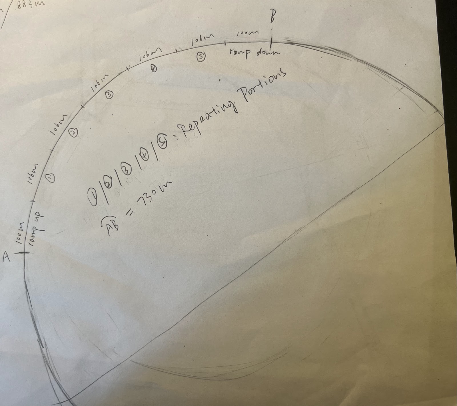
Overall Bridge Length
Step 5: Preliminary Model
The preliminary model will be built in Tinkercad. It starts with a bridge consisting of the starting ramp and the first section of the repeating structure. Then, I duplicate the repeating part and adjust the seams and radians of the bridge so it matches the map. And we will have a complete rough model of the bridge!
Steps:
- Bridge floor

Dimensions see sketch
- Columns

Dimensions see sketch
- Cut & assemble

- First Draft


- Modify
I enhanced the tunnels and decreased the number of columns for the environment.
- Final preliminary model


Step 6: Final Model
- Insert Canvas
I measured the width and length of the bridge. And I scaled the map to 1:1000mm.
- Bridge Floor: Right Curve
The right curve is referring to the right side bridge floor where the bridge splits up at the Ocean City side. But notice that the bridge is curving in all directions and does not have a specific pattern, I need to define how it’s curving from the top and the side. This way, when I sweep the profile onto the curve, the bridge will look smoother and will not have unnecessary seams in between each block like the model in Tinkercad. So I take the Tinkercad model as a rough reference to sketch two lines stated above. It takes a lot of time to adjust and align.

Then, we need to combine those two lines into a single line. I extruded surfaces from those lines so the surfaces intersect with each other.

And I split bodies to get the surface with the combined line.

Create a new sketch on any plane and project on the line.

Finish right curve.
- Bridge Floor: Left Curve
This side is more challenging. Because two lanes of this bridge are supposed to cross above each other and make a DNA-like shape, I have to make sure the heights do actually alternate and have enough space for the tunnels. The bridges cannot intersect and the steepness of the bridge needs to be appropriate to walk on as well. And the top view will reference Tinkercad just like the one above.
Create lines for top view and side view.

Then, I repeat steps to create a line and adjust until desired, combine them.


Finish left curve.
- Sketch Bridge Floor
Dimensions are written in the sketch earlier. They have slight changes from my pencil draft. I also rounded out the edges so there will not be a huge seam between two lanes when they are close together side by side. 

- Extrude Bridge Floor
Extrude the sketches onto their corresponding guidelines.

- Ramps
Then I created the ramps at both ends. The only dimensions that will change about the sketch is several lines in the middle of the floor because it makes the ramps wider.

I also need paths for both of the ramps. However, both of them are horizontal to the original planes so I only need to sketch lines on a plane in the middle of the ramp sketches.

Extrude the sketch onto this line.

Copy this ramp to the other end. I noticed that the main bridge floors on this side are slanted so the ramp cannot attach to them directly. I left a gap in between for transition floors.

- Transition Floors
This part is for connecting the ramp to the main bridge smoothly. Since the sketches don’t align with each other, I need to use “loft.” Also, there are two parts on the main bridge side but only one ramp. I need to split up the sketches into two parts for the ramp.


- Tunnels
Tunnels will be located at the space where the two bridges cross, in a rhombus-like shape from the top.
Create a plane along the bottom bridge path, at the start of the tunnel, perpendicular to the bottom bridge.

Sketch the cross section of the tunnel on this plane.

Extrude this sketch along the path of the lower bridge.

Extrude surface of the upper bridge edges and split body to get the middle portion. (*pictures are taken after materials have been applied)

- Columns
To create columns as sketched, I identified the locations first and created the bottom cylinders sketch with a diameter of 12mm for big columns and 8mm for small columns.

Extrude to 2 mm in height.

Sketch circles on top of the cylinders with a diameter of 5mm for small columns and 7mm for big columns. Extrude them to the bridge.

- Materials
I added materials for each part of the bridge.

This will be the final look of the bridge.


Step 7:
To stress test the bridge, I used the simulation function in fusion 360. So I created a mesh first.

The average pressure of a man standing is 70kPa. Assume that there is one person standing on every meter square on the bridge surface, then there will be 70kPa every square meter. Since I scaled the bridge down to millimeters, the surface will also be smaller at a scale of 10E-6. Plug in and get 0.000070Pa per square millimeter. We need to consider the most extreme case so I took this number and multiplied it by 10 to get 0.00070Pa for the pressure. I applied the pressure on the bridge surface.
This is the first time stress test result:
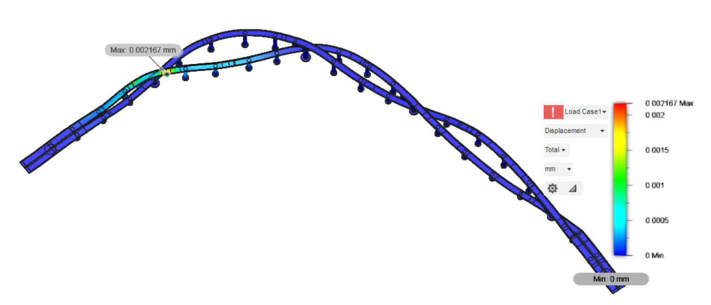
I adjusted the positions of the pillars in that warning area. Orange color disappeared. It is safe for people to walk on.

After rendering:

Step 8: Prototype
Materials:
- Foam board
- Acrylic paint
- Glow-in-the-dark paint
- 50cm ruler
- Hot glue gun
- White glue
- Clear glue
- White foam blocks
- Scissors
- Paint brushes
- Clay
- Micro landscape moss, human figures, boat, life buoys
- Tapes with patterns
- Toothpicks
- Straws
- Glitters

Map for reference.
 Roughly sketch the bridge, the jetty and islands on the foam board.

Use paper towel and glue to create seawave effects for the ocean.

More seawaves until they cover the whole sea area.

Use foam blocks to cut out islands representing Ocean City and Assateague Island. Then hot glue them to their locations.

Use paper towel and glue to make jetties.

Mix clear glue with green and blue glitters, pour it onto the paper towel area.

Until it looks like this.

Add details to the map for sea sprays and dirt.

Until it looks like this.

It’s time for the bridge model. Cut open a cardboard box.

Cut out strips for ramps.

And two strips for the main bridge floor, each 1 cm in width, twist them into desired shape and glue them together.

Use paper to make handrails. Shaded part should be glued to the bridge for attachment.

Attach handrails to the bridge.

Extend the handrails to the end of the bridge.
 Tape the bridge floor with white wood pattern tapes. Tape the handrails with black tape with glitters. They resemble the material I used in Fusion 360.

Tape to the end of the bridge.

Use clay and stick it onto the back of the bridge. It gives color and material consistency and extra support to the bridge.

Until it looks like this.

Paint the clay with gray color.

Cut open a plastic paint brush package for tunnels.

Shape it until it looks like this.

Cut it so it fits where the two lanes overlap. Paint it with blue.

Use straws and clay to make pillars. Paint them blue.

Attach main pillars to the bridge to secure the model. Then add the rest of the pillars.

Use clay and toothpicks to make a sensor and scent diffuser for horses.

Pillars and sensor placed as in the picture above.

Use thin steel wire and fake moss to make trees.

Make a line of trees.

Vegetation for Assateague Island can also be done using fake moss.

Little origami boat for decoration.
Finish Result:

Step 9: Conclusion
Thank you so much for sticking with me and hope my little creation can bring some inspirations to our lives.
Anna Zhang
Grand Prize in the
Make It Bridge


4 Comments
9 hours ago
Very nice design and lots of thought given to the process. Excellent models and visuals.
Maybe for the horse end, you could also look at creating an exclusion zone ahead of the sensor using "Cattleguards" which are ditches with lateral pipes across them. Cattle, horses, and any other ungulates will avoid crossing those.
3 days ago
Great Job, I love the overlay design!!!1
4 weeks ago
Fantastique travail ! Félicitations. 👍👍👍
5 weeks ago
Thanks for sharing! This is well thought out :)