
Introduction: Make Your Own Wireless Bluetooth Vintage Headphones!


Hello fellow makers,
A few years ago I was lucky enough to win a online auction for two pairs of vintage headphones at a ridiculous price of $0.01!
While both pairs looked basically new and worked, the old 8ohm drivers did not stand the test of time as well and was not easy to drive on mobile devices so they sat on my shelf as display pieces.
In need of another pair of wireless headphones I decided it was time to have a go at transforming one of these old beauties into something I can use on a daily basis instead of gathering dust.
Let's get making...
If you enjoy my Instructables and would like to support my future projects you can Buy Me A Coffee.
Supplies

To replicate this Instructable you will need:


- A pair of vintage headphones - Amazon link to something similar
- Access to a 3D printer - Amazon link
- A donor pair of headphones
or
- 40mm Drivers - Amazon link
- TP4056 charging and protection module - Amazon link
- *MH-M18 Bluetooth module
Found this as an alternative
Bluetooth 5.0 module made for headphones and has good reviews - Amazon link
- 16340 Li-ion battery - Amazon link
- Latching button - Amazon link
- Soldering iron and solder - Amazon linkHighly recommended!
- Wires - Amazon link


Step 1: Meet Frankenstein:

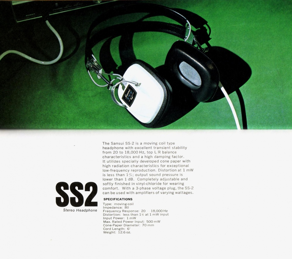
In this Instructable we will be transforming a pair of iconic Sansui SS-2's.
(These models are also quite readily available on auction sites)
Out of the two pairs I chose the Sansui's as they have have a beautiful vintage look, they are solidly built and these exact models have been used by ABBA during recording!
Step 2: The Donor:

Now you'd probably think I would want to use some nice new high end speaker drivers in this build but truth be told I bought these cheap iFrogz like 13 years ago and I absolutely loved their sound...even more than some of my higher end headphones, I loved them so much in fact that I continued to use them until they literally started disintegrating!
The speaker drivers in these were still brilliant I knew I wanted to use them for this project.
As the structure of these headphones had no life left in them I didn't have to be careful in the disassembly process and could just pop off any covers with a small flat head screwdriver until I found the 3 little screws that held the ear cups together.

Removing these three screws allowed access to the speakers that are just held in place by some adhesive that I simply scrapped away with a hobby knife in order to release them.
Step 3: Disassembling the SS-2's:

Now with these I had to be a lot more careful as I had no idea in what condition the plastics would be and if the vinyl will still be stretchable.
As it is currently winter here as I'm writing this Instructable the vinyl of the earpads was incredibly hard due to the temperature and I feared trying to stretch them over the lip of the ear cup would cause a tear and replacements for them would be near impossible to find.
To help with the removal I set the temperature of my soldering stations heatgun to 150degC and warmed up the pads to make them soft and stretchy, now I could simply pull them off starting at a corner with no problems.

Next step is the grills that also have the drivers mounted to them.
The grill is attached to the ear cups with four brass rivets and there is also four of the same rivets holding the driver in place, by using a sharp 3mm drill bit (I used it in my Dremel) we can simply drill the caps off of off the rivets to release them.
I first drilled the grills loose and removed them with the drivers and then drilled the rivets of the drivers as I didn't want to risk damaging the cups if I accidentally drill through the grill.

The existing wires from the headphones can simply be cut as we need four wires instead of the original two so we won't be reusing them.
Finally you can simply unclip the plastic cups from the metal brackets on the sides by simply pushing the brackets slightly open.
Step 4: Design and Print the New Speaker Assemblies:


As always when designing a part for 3D printing I turn to Fusion 360.
To make the design process a lot easier I scanned the bottom of the earcup along with a ruler for quick and accurate calibration as well taking a photo of the side profile.
With these images on hand I could use Fusion 360's insert Canvas feature to insert them into my workspace and by right clicking on the canvas and using "Calibrate" along with the ruler I scanned we get a very accurate base to sketch our design for the new driver and electronic mounting plates on.

My design uses 40mm drivers which is very common in modern headphones, bigger drivers might start running into some spacing problems.
I printed my parts using PETG but as the parts won't get directly exposed to any significant temperatures they can easily be printed in PLA filament.
Vintage headphones BT
Attachments


Step 5: Assembly: Part 1 - the Speakers and Headband


With our 3D printed parts finished we can start the assembly process.
I first want to adhere the drivers into the 3D printed parts using some B-6000 glue around each one, be careful when inserting the drivers into the cavities they will fit quite snug but you don't want to force them in as it might deform the membrane. If the fit is too tight just slightly enlarge it with some sanding paper.

Next we want to replace the old wires running through the headband with some new ones.
Lucky for us on the Sansui's this is an easy job as the wires simply run through a seam in the headband and can simply be pulled through from one side. The replacement wire I used is 22AWG 4 pin RGB wire that is simply separated down the middle into to 2 pin cables, the 22AWG fit perfectly down the seam and through the factory holes and I like the bit of color it adds.
Leave around 100mm of excess wire on each side of the headband to make soldering easier.
Step 6: Assembly: Part 2 - the Electronics


Time to get the electronics sorted.
I used a MH-M18 bluetooth module in my build but unfortunately after testing it was very quite and that's because the module is meant to be a line-in bluetooth device and not to directly drive headphones, to solve this problem while waiting for another module to arrive I dived into my parts bin and found a bag of 50 TDA2822 amplifiers I bought a while ago to experiment with. While it works for now this is definitely not a hifi setup and I would suggest using a module meant for headphone use like the MH-M28 or the one I linked in the supplies section (just make sure of the size as that is why I was initially drawn to the MH-M18).
The capacitor I added onto the speaker driver will also not be necessary when using a different bluetooth module.
To fit the space in the headphone I had to heat up the micro USB ports (you can also get this module with USB-C) mounting tabs (the two tabs on the side of the port) with a soldering iron and angled it slightly upwards as pictured, then resoldered both sides.

Now on the "left" ear assembly plate you can attach the TP4056 charging board onto the angled post and also mount the bluetooth module. To attach the models I used my old trusty B-6000 glue.
As the bluetooth modules have only a single ground terminal a lot of the time that multiple wires have to connect to I added a strip of copper tape that was then soldered to my ground pin to make wiring easier.

Solder wires from the OUT+ pad on the TP4056 to the VIN or V+ tab on your bluetooth module and then from the OUT+ on the TP4056 to the GND/Ground pad on the bluetooth module, you can also go ahead and solder the left drivers wires onto the left output of the bluetooth module.
Step 7: Assembly: Part 3 - the Wiring

To save space for the electronics I decided to put the battery on the right, this also helps to distribute the weight between the two sides.
I went ahead and added a piece of heatshrink tubing over the two pairs of wires before feeding them into the cup through the original wiring hole to protect them from excessive bending and it also looks a lot more proffesional.
The one pair of wires that was fed through the headband gets soldered to the battery (make sure the other side of the wires are not touching to avoid shorting the battery).
The second pair of wires gets soldered onto the speaker driver on the right assembly.

Once the wires have all been soldered to the right side cup I add the retaining clip back over the wires and pull the excess wire through the headband to the other side to solder to the left cup assembly.

On the left cup assembly we solder the positive wire that comes from the battery onto our switch which then goes to the BAT+ on the TP4056 module. The negative/ground from the driver and the battery both go to the ground tab I created earlier and the drivers positive goes to your amplifier/bluetooth modules right output.
Step 8: Assembly: Part 4 - Putting It All Back Together


Assembling of the headphones will be even easier than the disassembly because (cringe if you want but I have good reason to 🤣) I used hot melt glue, I will switch to something more permanent after installing the new bluetooth module and listening to it for a while to make sure everything is functioning correctly, but for now with the hot melt glue I can simply add a drop of alcohol to easily disassemble.
Make sure to heat up the earpads again when reassembling to avoid any tears.
Even if your battery is full you will need to plug in a charger for a second to activate the BMS protection of the TP4056, sometimes I forget this and struggle to figure out why there is no power.

Step 9: Enjoy Your Creation!

I hope you guys find this Instructable useful and if you have any questions please feel free to leave me a message or comment bellow.
Thank you for taking the time to read through my project and as always..
Happy making!
---

Participated in the
Battery-Powered Contest


Comments