
Introduction: Doppler Radar Telegram Critter Cam for Under $10!


Hello fellow makers!
In this Instructable I will be showing you how to make your own Telegram enabled critter cam using the ridiculously cheap ESP32-CAM board and a rcwl-0516 doppler radar sensor that will connect to your home WiFi network and send through photos of any movement in your yard straight to your Telegram account.
With this setup you don't have to struggle with SD cards like most of the trail cameras available plus you can instantly see any movement in your yard from anywhere in the world and you can even share the telegram link to friends and family.
Join me to learn how to build the camera setup, code the ESP32 and how to setup a custom Telegram Bot.
![]()
If you enjoy my Instructables and would like to support my future projects you can Buy Me A Coffee.
Step 1: What You Will Need:

To make your own Telegram enabled critter cam you will need:


- ESP32-CAM Board
Amazon - 2x ESP32-CAM modules with programming boards
- RCWL-0516 Motion detection module
- Access to a 3D printer or printing service
Amazon - Ender 3 v2 3D Printer
- PETG, ASA or ABS filament (PLA filament will not last long outdoors)
Amazon - OVERTURE PETG Filament 1.75mm
- Arduino IDE software
I use version 1.8.19
- Arduino Uno/Nano or FTDI programmer if you don't have the ESP32-CAM programmer board
*OptionalAmazon - Uno clone board
- Small 5V Solar panel with diode
Amazon - 80mm X 45mm 5v Solar panels
- 18650 Li-ion battery (good quality with protection preferably)
Amazon - Samsung 25R 3.7V Rechargeable 18650 Battery
- 18650 Battery tabs
Amazon - 50Pcs 18650 Battery Spring Contact Plate
- B-6000 Glue
Amazon - B-6000 Clear glue 25g
- 22 Gauge wire(at least 3 colors)
Amazon - 22 AWG Stranded Electrical Wire 22 Gauge


*As an Amazon Associate I receive a small percentage from sales made through provided links at no cost to you, this helps fund future projects.
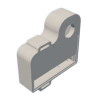
Step 2: Design and Print the Enclosure:


As always I turned to Fusion 360 for the design of the enclosure.

The enclosure is split into four pieces:
- The main enclosure
- The back cover
- The battery lid
- and The sun shield
Only the back cover and battery lid will need supports as the hinge parts are not touching the bed, I recommend that you print all of the parts with either PETG or ABS(ASA) filament to stand up to the elements outside.
I printed these using SBS witch is a derivative of ABS with a more rubbery property and works wonderful for rugged parts.
Included below is the STL's for all the parts including the STEP file, feel free to customize as required.
CritterCam
Attachments


Step 3: Coding the ESP32:

Below is the standard code for the Critter Cam, without modification this code will take a picture every time motion is detected and send the picture to your Telegram account.
IMPORTANT: I found that the newest version of the ESP32 package on "Board manager" in the Arduino IDE gives a problem with Telegram, to ensure the code works install package version 1.0.4

// Enter your WiFi ssid and password
const char* ssid     = "*****";   //WIFI SSID
const char* password = "*****";   //WIFI password
String token = "*****";
String chat_id = "*****";


#include <WiFi.h>
#include <WiFiClientSecure.h>
#include "soc/soc.h"
#include "soc/rtc_cntl_reg.h"
#include "esp_camera.h"


//CAMERA_MODEL_AI_THINKER
#define PWDN_GPIO_NUM     32
#define RESET_GPIO_NUM    -1
#define XCLK_GPIO_NUM      0
#define SIOD_GPIO_NUM     26
#define SIOC_GPIO_NUM     27
#define Y9_GPIO_NUM       35
#define Y8_GPIO_NUM       34
#define Y7_GPIO_NUM       39
#define Y6_GPIO_NUM       36
#define Y5_GPIO_NUM       21
#define Y4_GPIO_NUM       19
#define Y3_GPIO_NUM       18
#define Y2_GPIO_NUM        5
#define VSYNC_GPIO_NUM    25
#define HREF_GPIO_NUM     23
#define PCLK_GPIO_NUM     22


int gpioPIR = 13;   //Motion Sensor


void setup()
{
  WRITE_PERI_REG(RTC_CNTL_BROWN_OUT_REG, 0);

  Serial.begin(115200);
  delay(10);
  WiFi.mode(WIFI_STA);
  Serial.println("");
  Serial.print("Connecting to ");
  Serial.println(ssid);
  WiFi.begin(ssid, password);
  long int StartTime=millis();
  while (WiFi.status() != WL_CONNECTED)
  {
    delay(500);
    if ((StartTime+10000) < millis()) break;
  }


  Serial.println("");
  Serial.println("STAIP address: ");
  Serial.println(WiFi.localIP());
  Serial.println("");


  if (WiFi.status() != WL_CONNECTED) {
    Serial.println("Reset");

    ledcAttachPin(4, 3);
    ledcSetup(3, 5000, 8);
    ledcWrite(3,10);
    delay(200);
    ledcWrite(3,0);
    delay(200);
    ledcDetachPin(3);
    delay(1000);
    ESP.restart();
  }
  else
  {
    ledcAttachPin(4, 3);
    ledcSetup(3, 5000, 8);
    for (int i=0;i<5;i++) {
      ledcWrite(3,10);
      delay(200);
      ledcWrite(3,0);
      delay(200);
    }
    ledcDetachPin(3);
  }


  camera_config_t config;
  config.ledc_channel = LEDC_CHANNEL_0;
  config.ledc_timer = LEDC_TIMER_0;
  config.pin_d0 = Y2_GPIO_NUM;
  config.pin_d1 = Y3_GPIO_NUM;
  config.pin_d2 = Y4_GPIO_NUM;
  config.pin_d3 = Y5_GPIO_NUM;
  config.pin_d4 = Y6_GPIO_NUM;
  config.pin_d5 = Y7_GPIO_NUM;
  config.pin_d6 = Y8_GPIO_NUM;
  config.pin_d7 = Y9_GPIO_NUM;
  config.pin_xclk = XCLK_GPIO_NUM;
  config.pin_pclk = PCLK_GPIO_NUM;
  config.pin_vsync = VSYNC_GPIO_NUM;
  config.pin_href = HREF_GPIO_NUM;
  config.pin_sscb_sda = SIOD_GPIO_NUM;
  config.pin_sscb_scl = SIOC_GPIO_NUM;
  config.pin_pwdn = PWDN_GPIO_NUM;
  config.pin_reset = RESET_GPIO_NUM;
  config.xclk_freq_hz = 20000000;
  config.pixel_format = PIXFORMAT_JPEG;


  if(psramFound())
{
    config.frame_size = FRAMESIZE_VGA;
    config.jpeg_quality = 10;  //0-63 lower number means higher quality
    config.fb_count = 2;
  }
else
{
    config.frame_size = FRAMESIZE_QQVGA;
    config.jpeg_quality = 12;  //0-63 lower number means higher quality
    config.fb_count = 1;
  }

  // camera init
  esp_err_t err = esp_camera_init(&config);
  if (err != ESP_OK)
{
    Serial.printf("Camera init failed with error 0x%x", err);
    delay(1000);
    ESP.restart();
  }


sensor_t * s = esp_camera_sensor_get();
 s->set_framesize(s, FRAMESIZE_XGA);


}


void loop()
{

  pinMode(gpioPIR, INPUT_PULLUP);
  int v = digitalRead(gpioPIR);
  Serial.println(v);
  if (v==1)
  {
    alerts2Telegram(token, chat_id);
    delay(10000);
  }
  delay(1000);

}


String alerts2Telegram(String token, String chat_id)
{

  const char* myDomain = "api.telegram.org";
  String getAll="", getBody = "";


  camera_fb_t * fb = NULL;
  fb = esp_camera_fb_get();
  if(!fb)
{
    Serial.println("Camera capture failed");
    delay(1000);
    ESP.restart();
    return "Camera capture failed";
  }


WiFiClientSecure client_tcp;

  if (client_tcp.connect(myDomain, 443))
{
    Serial.println("Connected to " + String(myDomain));

    String head = "--India\r\nContent-Disposition: form-data; name=\"chat_id\"; \r\n\r\n" + chat_id + "\r\n--India\r\nContent-Disposition: form-data; name=\"photo\"; filename=\"esp32-cam.jpg\"\r\nContent-Type: image/jpeg\r\n\r\n";
    String tail = "\r\n--India--\r\n";


    uint16_t imageLen = fb->len;
    uint16_t extraLen = head.length() + tail.length();
    uint16_t totalLen = imageLen + extraLen;

    client_tcp.println("POST /bot"+token+"/sendPhoto HTTP/1.1");
    client_tcp.println("Host: " + String(myDomain));
    client_tcp.println("Content-Length: " + String(totalLen));
    client_tcp.println("Content-Type: multipart/form-data; boundary=India");
    client_tcp.println();
    client_tcp.print(head);

    uint8_t *fbBuf = fb->buf;
    size_t fbLen = fb->len;


    for (size_t n=0;n<fbLen;n=n+1024)
 {


      if (n+1024<fbLen)
{
        client_tcp.write(fbBuf, 1024);
        fbBuf += 1024;
      }
      else if (fbLen%1024>0)
{
        size_t remainder = fbLen%1024;
        client_tcp.write(fbBuf, remainder);
      }
    }

    client_tcp.print(tail);

    esp_camera_fb_return(fb);

    int waitTime = 10000;   // timeout 10 seconds
    long startTime = millis();
    boolean state = false;

    while ((startTime + waitTime) > millis())
    {
      Serial.print(".");
      delay(100);
      while (client_tcp.available())
      {
          char c = client_tcp.read();
          if (c == '\n')
          {
            if (getAll.length()==0) state=true;
            getAll = "";
          }
          else if (c != '\r')
            getAll += String(c);
          if (state==true) getBody += String(c);
          startTime = millis();
       }
       if (getBody.length()>0) break;
    }
    client_tcp.stop();
    Serial.println(getBody);
  }
  else {
    getBody = "Connection to telegram failed.";
    Serial.println("Connection to telegram failed.");
  }

  return getBody;
}
How to create a Telegram Bot:
Step 1: Open Telegram and search for Bot father. Click on start. then send a message “/newbot”
Step 2: It will ask you name for the bot, Simply Give a name for your bot, I named my bot as “CritterCam”
Step 3: Again It will ask you the username for the bot, Enter the username for the bot, I give it as “CritterCam_bot” After entering a username, you will get the token, That’s it, click on the token and it will be automatically copied to clipboard then save it for future use.
Note: make sure that the username has to be unique, it should end with “bot” and there will be no empty spaces or dots because it will consider as an invalid username.
Step 4: Return to the main page of Telegram, and search for the bot with full name. In my case it is “CritterCam”, then start it.
Step 5: Now, again come back to the main page of Telegram, and search for “Get My ID”, and start it. within a few seconds, you will receive Chat ID. Save this chat ID along with Token. That’s it, we have successfully set up the Telegram to receive the notifications.
Step 6: You can now go ahead and enter this into the code before uploading to the ESP32.
Step 4: Start Assembly:

Before we can continue we need to assemble the lens cover.

In this build I used a aluminium bevelled glass lens cover that was salvaged from an old broken CCTV camera, these are plentiful at metal recycling centres and are a great source for 12mm lenses for all your camera related projects as well as tons of IR LED's...more on that later
The lens cover I'm using simply pushes into place with some force within the 19mm hole in the design (I've disassembled a few CCTV cameras and this seems to be standard across the smaller cameras).
We can use some B-6000 glue to seal around the cover on the inside.

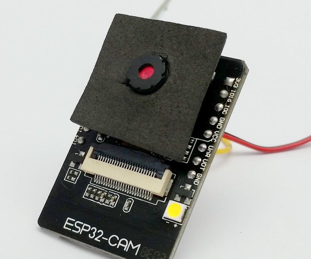
Next I cut out a small square of foam from some scraps to surround the camera sensor, this hides the electronics behind the sensor and also eliminates any reflections from the bright metal behind the sensor.
Step 5: Solder the Electronics:

Time to get our modules soldered together.
This is probably one of the least intimidating solder jobs I have done in a long time as there are so few wires to connect and it connects directly from pad to pad no special soldering magic required.
To get everything working for this project we only only need a power connection and a single signal wire...That's it!

Start by soldering on three differently colored wires onto your RCWL-0516 module, I have RED soldered onto the VIN pad, BLACK soldered onto the GND pad and a YELLOW wire soldered onto the OUT pad.
From there we solder the RED wire onto the 5V pad on the ESP32-CAM module, the BLACK wire gets soldered onto the GND pad and the YELLOW wire gets soldered onto the IO13 (changed it to IO13 the diagram still shows IO12).
Note that I also soldered an additional 5V and GND wire onto the ESP32-CAM modules pads as this will go to the battery tabs.

Step 6: The Solar Panel & Battery Tabs:


Now that the two main modules are soldered together we will need to provide them with a power source.
When starting this project I never intended the camera to be left outside unattended for multiple days, so I designed it to be powered from a single removable 18650 and a quality name brand cell easily provides us with 24 hours of working time but just so that we don't deplete the cell every time and as such increase our battery's lifecycles I decided to add a inexpensive small 5V solar cell in parallel with the battery.
If you prefer you can use a battery with a built in protection circuit but as the solar cell is only there to assist and is too weak to ever really charge the battery it shouldn't be necessary.

I used some 2 part CA glue to glue the small 85mm X 45mm solar panel in place after feeding the wires into the enclosure.
We then need to solder the leads from the solar panel to battery tabs that our 18650 battery will connect to, the positive wire from the solar panel goes to the flat battery tab and the negative/GND wire from the solar panel goes to the tab with the spring attached.

Next we need to solder on the power wires from the ESP32 module to the battery tabs, there are two slits on either side for the wires to lay flat in.
I used black hotmelt glue to waterproof the back of the solar panel and also hide any excess wires.

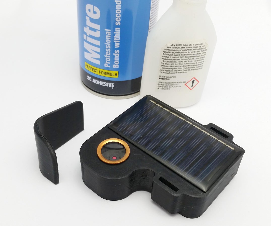
Step 7: Finish the Assembly:


We can now put everything together.
For the hinge pin of the battery lid I simply used a piece of printing filament cut about 6mm longer than the hinge and then simply heated both ends of the filament with a lighter flame and squished it with my finger to prevent it from sliding out.

Next I applied a bead of B-6000 glue all around the seam of the enclosure and pressed the back cover into place, the B-6000 will fill any cavities and give us a weatherproof seal.

And finally we need to adhere the sun shield to the top of our camera housing. I used 2 part CA glue to permanently adhere it to the camera body, the shield will help debris from getting onto the lens and also prevent some sun glare.
You can now add either a strap or elastic through the mounting holes and start using your critter cam!
Step 8: Sample Images:
*Coming soon
Step 9: The IR Version:

My next iteration of the critter cam will include IR LED's that will allow us to catch some creatures of the night in action.
Unfortunately for us to take pictures in complete darkness we will need to remove the IR blocking lens that is present in the standard ESP32-CAM module's lens stack, I find it easier to modify the original sensor in order to use readily available 12mm lenses than trying to remove the IR blocking element from the original lens.

As you can see the red IR blocking lens is the last of the stack.
If you want more information on fitting a 12mm lens you can have a look in my Instructable "Kodak Brownie Digital Camera" where I modified the original sensor of the ESP32-CAM.
Critter Cam
Step 10: Enjoy!


I hope you guys find this Instructable useful and if you have any questions please feel free to leave me a message or comment bellow.
Thank you for taking the time to read through my project and as always..
Happy making!
---

Participated in the
For the Yard


21 Comments
Question 8 days ago
Do you have any examples of what the results of this build are? Like what do you see in your telegram account?
22 days ago
Great Project, in fact I just having all stuff right here just the lens cover is missing. I found some cover glass flash lights: https://de.aliexpress.com/item/1005002206975003.ht...
Does anyone have a better idea?
25 days ago
What keeps the solar cell from ultimately draining the battery? Shouldn't there be a blocking diode in there, somewhere?
Reply 24 days ago
To be fair, the shopping list does mention "solar panel with diode", though the Amazon link goes to a product that doesn't' indicate if the diode is built-in.
I'm more concerned for the fact that there's no BMS for that single Li-ion battery. I think it would be wasteful to not have a BMS and keep the battery healthy as long as possible.
Reply 24 days ago
True dat! I've been getting spoiled on using cells that have a BMS built-in, lately.
Reply 23 days ago
While some Li ion batteries have built-in BMS circuits, this particular battery in this Instructable (the Samsung 25R) is unprotected and requires an external BMS. Either this kit will eventually kill 18650s or cause them to explode.
Reply 23 days ago
Yeah... I know.
23 days ago
I would add a TP 4056 charging modules such as the attached link to protect and properly charge the 18650 battery. Place it between the 5V solar panel and the battery.
https://www.amazon.in/ICSTORE-TP4056-lithium-battery-charging/dp/B082YVLP35
26 days ago
I think there was a misprint on the cost to build the Doppler detector, instead of 10
dollars it should read a thousand dollars.
Reply 24 days ago
I am more than happy to supply you one of the sensors specified in the projec5 above at a special price that will save you fortune. The cost to you is just £100…ooops $100. Is that ok. And I will even throw in free international posting. Just let me know.
Question 25 days ago on Step 10
Hi.. I am just trying out the software and managed to get it working with Telegram. However when it sends a picture I seem to get the very top few lines of the picture (about an eighth of whole picure), and nothing else. Just wondering if you have any tips to allow the whole picture to be sent /recieved. Excellent tip about esp32 version of board to use.... mine refused to work on the later ESP32-cam boards either.. so just used the esp32 dev board. Thanks for a great Project which I intend to use for a couple of future projects.
Answer 24 days ago
Thank you :)
That's very strange, could it perhaps be related to flash memory of the dev board? I have no idea how they compare to the regular cam modules.
Reply 24 days ago
Yep … it must be to do with the psram on board or sensing it.. my esp32-cam board would appear to be a different type to the one you used. I found the solution and just it just a simple change to the setting on the resolution in your code.
in the code it sets the frame size…
if(psramFound())
{
config.frame_size = FRAMESIZE_VGA;
config.jpeg_quality = 10; //0-63 lower number means higher quality config.fb_count = 2;
}
else
{
config.frame_size = FRAMESIZE_QQVGA;
config.jpeg_quality = 12; //0-63 lower number means higher quality config.fb_count = 1;
}
I just changed the QQVGA to VGA and it all works… it still needed the fb_count set to 1.
Thanks.
Derek
4 weeks ago on Step 10
I am *definately* prototyping this soon; I have all these parts in my Lab especially the esp-cam and the 10GHz RCWL radar body doppler detector. What I would not have thought of was integration with telegram and the Solar +18650 combo for remote yard placement. I have to get a log-periodic antenna so that this camera can transmit the 850m back to the farm house and I am all set. Thanks for this outline; I will take it from here based on your reference integration. best regards to Jamie. John (Canada, Electronics Technologist 44th year)
ps: I already bought IR enhanced ESP32Cam dev boards from friends in Guangdong last year (10 I think)
Reply 24 days ago
Thank you for taking the time to read through my project. Having the IR board makes it so much more useful!
26 days ago
Under $10 You say? The 18650 battery alone costs 7€ here in EU.
Reply 24 days ago
I feel your pain, the prices here in South Africa is just as ridiculous, as most of the audience is usually US based I went according to Amazon.
25 days ago
Excellent project, great job! Are you not worried about over charging the battery?
Reply 24 days ago
Thank you very much, if the camera had a power switch I would add a BMS just for safety but like it functions now where it's on when a battery is inserted I'm not worried about it as the consumption is 20% more than the maximum output of the panel so it will never really charge the battery.
26 days ago
I am concerned about the solar battery conection. The 18650 specified does not seem to be "protected" from over charging from the 5 Volt 70ma solar cell. From what I can find on the 18650 the output range is from 2.5v to 4.2v. I don't think the esp32 is going to run very well(if at all) on max of 4.2v from the battery when the specs say the AMS1117 shows that it requires a minimum of 4.8V to achieve the 3.3V needed for the ESP32.