
Introduction: Modular-Mechanical Rocket

Hi! My name is Inaki Iturriaga, I'm 15 years old and I go to Cardenal Newman School in Buenos Aires, Argentina.
Allow me to introduce you to my invention: A Modular Mechanical Payload-Ejecting rocket. Made entirely through 3D printing, this rocket showcases a modular design, consisting of 6 distinct body sections which can be separated to work on each individual part, a set of 6 fins ensuring flight stability, and a two-component nosecone.
I made this because where I live building model rockets is a struggle, and things like Estes motors and Kits are extremely difficult to come by. I want to make this hobby more accesible and and inclusive for individuals in similar situations.
The primary objective of this model rocket is to climb to an altitude of 1000 meters, followed by the deployment of a compact satellite—akin in size to a standard beverage can.
While it's common to find most model rockets utilizing delayed detonations to eject payloads or parachutes, this one employs a rack and pinion system, allowing for a more precisely controlled ejection.
To get started, we'll delve into the theoretical design and the mathematics that make this rocket possible. Then we'll navigate through the design process on Fusion 360 and into the specifics of the printing process. Finally, we will embark on a step-by-step exploration of the assembly process, and work the mechanics behind the ejection system.
So, are you ready? Let's dive in!
Step 1: Design and Simulations


Before we begin, we must define the components used. The motor for the rocket, will be the B200 KNDX (Potassium Nitrate and Dextrose based propellant) designed by Richard Nakka. Its has a thrust of 1157 Newtons, which makes it fall into the "H" class. It weighs around 400 grams when loaded with the propellant and has a burn time of 0.38 seconds.
We'll use OpenRocket, an opensource rocketry software, to calculate the stability of the rocket.
After placing each of the components with their materials and densities, we get a cal (Stability measure) calculation, For this rocket we're aiming for 1.2 to 2 cal. Now knowing that the rocket is stable, we can go ahead and simulate its performance. As we're not using a factory produced motor, its better to do the math by hand.
We can use the equations provided in Rocketmime.com to determine the max height and speed.
- M = Mass
- M = 1.5kg
- A = Area
- A = pi * (0.5 * (diameter in inches / 12) * 0.3048)²
- A = 3.1415926 * (0.5 * (2.75 / 12) * 0,3048)²
- A = 0.00383 m²
- K = Wind Resistance Factor
- K = 0.5 * rho * Cd * A
- rho and Cd are constants, in this case, 1,2 and 0,75
- K = 0.5 * 1.2 * 0.75 * 0.00383
- K = 0.0017235
- g = Gravitational Force
- g = 9.8 m/s
- T = Thrust
- T = 1157 N
- t = Burn Time
- 0.38 s
- q
- q = sqrt ((T - M * g) / k)
- q = √((1157 - 1.5 * 9.8) / 0.0017235)
- q = 814.11
- x
- x = 2 * k * q / M
- x = 2 * 0.0017235 * 814.11 / 1.5
- x = 1.87
- V (Velocity at burnout)
- V = q * (1 - exp(-x * t)) / (1 + exp(-x * t))
- V = 814.11 * (1 - exp(-1.87 * 0.38)) / (1 + exp(-.87 * 0.38))
- V 277 m/s
- yb (Altitude at Burnout)
- yb = (-M / (2 * k)) * ln ((T - M * g - K * V²) / (T - M * g)
- yb = (-1.5 / (2 * 0.0017235)) * ln ((1157 - 1.5 * 9.8 - 0.0017235 * 277²) / (1157 - 1.5 * 9.8))
- yb = 53.54
- yc (Altitude after Burnout)
- yc = (M / (2 * k)) * ln ((M * g + k * v²) / (M * g)
- yc = (1.5 / (2 * 0.0017235)) * ln ((1.5 * 9.8 + 0.0017235 * 277²) / (1.5 * 9.8)
- yc = 1001.82
- Max Altitude
- Max Altitude = yb + yc
- Max Altitude = 53 + 1001
- Max Altitude = 1054m
So after completing the equations, we get a Max Altitude of 1050 meters and a Max Velocity of 277m/s which equates to 0.8 times the speed of sound!
Having this data is crucial for the design of the rocket such as the fins and distributing the weight.
Step 2: Designing the Fins


Now we can start designing on Fusion 360!
- Make a new sketch and create a square with the dimensions of the fins. In this case, 150mm x 50mm.
- Use the insert canvas function to paste a screenshot from openrocket into the square.
- Use lines to trace the shape of the fin and finish sketch
- Use extrude to make a body out of the sketch. In this case, we need to extrude 2mm
- Create a circular pattern to create the 5 other fins.
Step 3: Designing the Nosecone


- Create a new sketch on the X axis and make a circle. In this case, 65 mm wide.
- Finish sketch and use the extrude function to create the nosecone shoulder. The shoulder is the part which is inserted into the rocket body and holds the nosecone in place. In this case, 20 mm in height.
- Now create a new sketch in the Y axis. Create a square as with the fins and paste a screenshot of the the nozzle from open rocket. In this case, the square should be 200mm x 70mm
- Use the Fit Point Spline to trace the shape of the nosecone. Leave a 2mm space beetween the lines.
- Finish sketch and use the revolve function, press one of the sides and make a 360 deg angle, choose as the axis the X axis and hit OK.
Step 4: Designing the Body


- Create a new sketch on the X axis, right between the fins. Make a circle, in this case, 70mm wide.
- Use the offset function and create an inner circle at -2mm. Then Finish Sketch.
- To make it fit most printers, use extrude to create a 140mm cylinder
- Repeat last step 4 more times, creating new bodies from the last
- Finally create a sixth cyilinder, this time, 100mm tall.
- By now you should have 6 cylinders, one on top of the other, measuring an added height of 1 meter.
Step 5: Printing the Parts

Now its time to start the printing process!
The list of files to print for the rocket body:
- 5x Tube_140mm.stl
- 1x Tube_100mm.stl
- 1x NoseCone_1.stl
- 1x NoseCone_2.stl
- 2x Motor_Retainers.stl
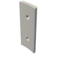
- 18x Body_Connectors.stl
- 6x Fins.stl
Files to print for the mechanical ejection system:
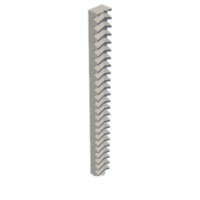
- 1x Rack.stl
- 1x Pinion.stl
For my rocket, I used normal PLA, at 200 degrees Celsius. The only part that needs support material is Nose_Cone1, the rest are ready to print.
Attachments


Step 6: Assembling of the Rocket


Now comes the hard part, assembly.
Assembling the body
- After printing every part, we must clean them from any remains from the printing process
- Now we're ready to start putting together the body. Grab the six cylinders and hold two of them together. Then grab one of the body connectors and place it in the middle of the two cylinders. The holes in the body connectors are meant for screws but if you incorporate print the cylinders with holes, the structural strength will be greatly debilitated. To make the holes, I recommend using a soldering iron.
- Use the heated tip to make a small hole through the cylinder, using the Body connectors as guides. Finally use screws to attach the connectors to the cylinders.
- Repeat step 3, until the first 5 cylinders are attached, the shorter one at the top and then followed by 4 of the normal ones. The sixth cylinder has to be attached with only two connectors so that the fins can be attached.
- Now the Body is finished! Its time to move on to the Fins.
- Using the Drawings function on Fusion 360, I made a schematic of the fins position which can be printed and used as a guide to hold the fins in place.
- To glue down the fins, I used some hot glue. Then, using the soldering iron, I welded the plastic from the cylinders to the fins for a strong bond.
- The nosecone just needs glueing the two parts, and some electrical tape can be applied to create a tighter fit when inserted into the body.
- The motor retainers are locked into place by the B200's screws. Some electrical tape can be applied to create a tight fit. The top retainer of the motor, is hold in place by the screws used on the second cylinder from the bottom.
And that's it! the rocket is ready for flight. It's only missing the ejection mechanism.
Attachments

Step 7: The Ejection Mechanism


The rocket is only missing the final piece, the ejection mechanism.
I'll show how to create the mechanism which can later be paired with an altimeter for control. This is just the base.
The mechanism consists of several parts:
- NodeMCU ESP8266 microcontroller
- 1:120 TT Gear Motor
- 9V battery
- KY-019 Relay module
To test the mechanism while on ground, I also added an optional Push Button.
The NodeMCU has an ESP8266 wifi module on-board which can also be used to test the systems from a distance.
I included an easy to read electronics schematic to use as a guide.
The NodeMCU must be programmed before hand so I also included an example code in c++. for Arduino.

Step 8: Final Product

Now the rocket is finally ready to fly!
It has taken me several months of planning and building but I believe that the final result is totally worth it.
It's important to keep in mind that any tests and launches should be made with complete precaution. Always be as far from the rocket as possible when powering on the motor.
Use the payload slot to create your own devices like satellites or can-sats, something fun or maybe just a coke can.
Please feel free to make any questions and I'll try my best to help you!
Good Luck!
Second Prize in the
3D Printing Student Design Challenge


Comments