
Introduction: Designing a Pedestrian Bridge

Hello! My name is Levi, and I am 14 years old. I am homeschooled in Chestermere, Alberta, Canada, and I just finished Grade 9. I will be documenting the process I used to replace an outdated pedestrian bridge in my community. I originally created this Instructable as an entry for the 2023 Make It Bridge: Student Design Challenge. Through the process, it became a great learning experience for me in civil engineering, Autodesk Inventor, and photogrammetry. This is not intended to teach you how to design the exact bridge that I designed, but rather a general process that you can adapt using the steps and skills demonstrated in this Instructable to design a pedestrian bridge to your own specifications.
I hope you enjoy this Instructable on designing a pedestrian bridge!
Supplies
Software:
- Autodesk ReCap Photo (free for students)
- Autodesk Inventor (free for students)
Equipment:
Required Skills:
- Knowledge of basic engineering terms (If there is a word or term you are unfamiliar with, check out Wikipedia's Glossary of civil engineering)
- Experience with Autodesk Inventor
Step 1: Finding the Location

If you want to build a bridge, you will need somewhere to put it! If you're designing a bridge for a client, you will usually be given either an exact location or a general area, in which the bridge is to be built. If you are given a general area you might need to take into account multiple factors such as terrain, walkway/road location, connecting infrastructure, accessibility, etc. to determine the exact location. For the purpose of this project, I had to choose a location in my community where the construction of a pedestrian bridge would positively impact the community.
After considering where I could construct a new bridge, I decided that I would redesign an outdated bridge that is used by many people in my community (myself included). This bridge is an integral part of a popular walking/biking path in the community of Chestermere. Chestermere is a lake community with a canal that runs through the city. This bridge is the only pedestrian bridge that connects the East and West communities together. Dog walkers, families, cyclists, and fishermen all frequently use this bridge. Although the bridge is currently functional, there are a variety of issues with the current bridge that I will address in the next step. There is also a large area shaded by trees; however, there are no benches or picnic tables for people to fully enjoy the space. This is also something that I will be improving in my design.
Step 2: Why the Bridge Needs to Be Replaced


There are a few issues I assessed with the current bridge that warranted the re-design and construction of a new bridge.
The deficiencies of the current bridge include:
- The wooden deck needs to be replaced often
- The metal frame is rusty
- There are very large gaps between the wooden planks
- Bollards (poles that stop vehicles from entering the bridge) are obtrusive to bikes, strollers, and wheelchairs
- Unappealing appearance
- The arched shape is difficult for cyclists who have to dismount to pass the bollards
While many of these issues are cosmetic and can be fixed by maintenance of the bridge, there are some that would require the bridge to be replaced, such as the wooden deck or the arched shape of the bridge. The bollards are also very problematic for accessibility, as people in wheelchairs and people with strollers can often not cross the bridge. The design of my bridge will allow for the inclusion of all members of this community.
Here is how I will be addressing these issues:
- Concrete deck to replace the wooden deck - this will require less maintenance, provide more traction, and have a much more even surface
- Rust-resistant paint
- Concrete "planks" that have small, even gaps to allow water to drain
- Removal of bollards
- Flat shape to improve accessibility
I believe these solutions would greatly improve the experience for the many people who use the bridge, along with providing access to those who were previously unable to access the current bridge.
Step 3: Aerial Photogrammetry - Part 1


Obtaining some form of real-world measurement data is a critical part of any construction project. There are many different types and fields of measurement. This isn't just limited to measuring distance; it could be the measurement of temperature, wind, precipitation, seismic activity, number of pedestrians, etc. For this project, I mainly focused on measuring distance using a process called aerial photogrammetry.
What is aerial photogrammetry? Photogrammetry is the process of taking physical measurements using photographic data, and the "aerial" part means the images are taken from the air (in this case using a drone). I used these images to construct a 3D model (pictured above) of the area in which I designed the bridge.
To accomplish this, I used two different things: Photogrammetry software (Autodesk ReCap Photo) and a drone with a camera and GPS. To get the final 3D model, it requires taking lots and lots of pictures of the area from different angles with your drone. I took a total of 100 pictures, as that is the maximum amount that ReCap Photo allows for students. After loading the images into ReCap Photo, the program generated a 3D model of the terrain. The program also generated an ortho photo (an image that has a top-down orthographic view of the area) that can be used for creating maps.
But how does this work? How can a group of images taken from different angles create a 3D model? The answer is complex, but basically the program uses a bunch of mathematical algorithms to detect which images contain the same objects and then uses those images to triangulate the 3D locations of the pixels in the images. Combine this with GPS data, and you have an accurate 3D model of whatever you scanned—properly scaled and with a known location. If you are interested in learning more about photogrammetry, there is a great video on drone photogrammetry here.
NOTE: Please be sure to be familiar with your local laws and regulations regarding UAVs (drones) and surveying. Many jurisdictions require obtaining a drone license to pilot certain drones. Surveying for the purpose of defining land boundaries (or, in certain jurisdictions, surveying in general) may also require special licenses.
Step 4: Aerial Photogrammetry - Part 2


Now that you understand aerial photogrammetry a little better, it's time for me to actually show you how to do it! The first thing you will need for this is Autodesk ReCap Photo (included with ReCap Pro). The other thing you will need is a drone with a camera and GPS (I used the DJI Mini 2, however, it has now been superseded by the DJI Mini 3).
Photographing the Area:
To get a good 3D model, you will need to take lots of pictures from different angles, keeping about 70% overlap between frames. Overcast/flat lighting is ideal. I took a total of 180 images of the area from various angles. Remember to make sure you have GPS enabled and that your drone geotags the images. If not, you will have to set the scale of the 3D model later, and this is usually not as accurate as having GPS.
Processing the Images Using ReCap:
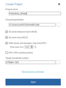
Once you have taken all your photos, you can add them to ReCap Photo. First, select the "Aerial" option, then select the photos you want to use. After you have selected all of your images, you may need to remove some of them if you are over the maximum number of images permitted. Click "Create", name your project, and then select the types of files you want to be outputted (I selected the mesh, point cloud, and ortho photo options). Then click "Start", and your project should begin processing. It will take a while (mine took a few hours), but when it is complete, you can view the final model (shown above in Step 3).
Step 5: Area Layout

This is how I chose to lay out the area for the new bridge. I wanted to build the new bridge in an offset location from the old one so that the current bridge and path could still be used during construction. The unpaved path leading up to the bridge should also be paved to allow easier cycling and wheelchair access. There could also be picnic tables added to the area, and more trees could be planted to increase shade. When the old bridge is removed, concrete stairs leading down to the water could be built to allow easier access to the canal below.
Step 6: Design Characteristics and Other Goals
After establishing a basis for where the new bridge will be built and why the old bridge needs to be replaced, the next step is to define some design characteristics for the new bridge. A few things I wanted to include were a flat concrete deck, the removal of bollards, and the steel painted the City's iconic blue colour. Another feature that I wanted to include was added lighting for the purpose of highlighting the bridge for safety and to make the bridge stand out visually.
Step 7: Brainstorming Rough Design Ideas


As part of the process, I brainstormed some mock-ups of different types and shapes of bridges. Please note that the drawings are not to scale and are purely for visualization purposes. Each bridge design is shown in two orthographic views: Side and Top-down.
1:
This is the design of the old bridge. As previously mentioned, the arch can be problematic for cyclists who have to dismount to enter the bridge because of the bollards and have to begin cycling at the bottom of an incline. The incline may not appear to be very steep; however, from the user's perspective, it can feel quite steep.
2:
This design was inspired by the observation that people often stop in the middle of the bridge to enjoy the view. My thought behind this design was that people who wanted to enjoy the view could stand out of the way of other pedestrians and cyclists by standing in the large lookout area. The main reason I chose not to use this design was due to structural issues. The large circle in the middle of the bridge would not be easily supported. It would also increase the weight of the structure, and the lookout would likely have the largest live load of pedestrians, adding to the structure's support challenges.
3:
A refined version of design 2. Instead of the large lookout in the middle of the bridge, why not spread it out evenly across the whole bridge? There are two reasons I did not choose this design: Structural reasons (similar issues to #2, though not as severe), and the problem that the "lookout" area is not very clearly defined, so it is less likely that people will actually use it with the design in mind.
4:
This is the design I chose to use. The Warren-truss design functions both as the handrail and as the main support for the bridge. The Warren truss is ideal for handling evenly distributed loads, which makes it excellent for bearing the large dead load of the concrete deck. I chose to use equilateral triangles for the truss as they are generally more aesthetically appealing. This is a pony truss or half-through truss design, meaning that it does not have struts connecting the truss joints on top of the railing. I chose this design because it is both geometrically interesting and structurally practical.
Step 8: 3D Design - Terrain


I chose to use the 3D photogrammetry model I made of the area to create a simpler CAD model that I could use as a reference to design my bridge. To do this, I took measurements from the model in ReCap Photo using the "measure distance" tool and created an Inventor sketch of the terrain using those measurements. I mainly did this for performance; a simple 3D model like this will use a lot less processing power than a detailed photogrammetry model.
Step 9: 3D Design - Frame: Part 1

In this step, I will show you how I made the frame of the bridge.
Sketching Out the Frame:
The first thing I did when designing the frame was sketch the truss shape in Inventor. I wanted the height of the handrail to be ~1.2m high. I also chose to use ANSI standard 12.1" high I-beams on top of the floor beams as stringers (beams going across the bridge in the direction of travel). The concrete bridge deck needed to be 7" thick to conform to national code.
Calculations:
With a handrail height of 1.2m from the bridge deck and 19.1" (12.1" beams + 7" concrete) of material below the top of the bridge deck, the truss will need to be ~1.685m (1.2m + 19.1") tall. I also wanted there to be a whole number of equilateral triangles in the truss. To fix this, I decided to slightly modify the height of the handrail to produce the correct number of triangles. I did some math to figure out how many triangles there would be with a height of 1.685m (there would be ~20.3 triangles) and then did the math to figure out the height of the truss for 20 equilateral triangles. The resulting height was 1.713m, an increase in height from my original target height of only about 2.8cm, or 1.1". A very useful feature in Inventor is the ability to specify which unit of measure you want to use in a dimension. This can be extremely time-saving in Canada when using pre-made steel components that are only available in Imperial units.
With the accurate measurements, I was able to sketch the truss in Inventor. First I created a 3D sketch, and using the "Front" view on the ViewCube, I started creating the rectangle that would contain the triangles. I made this rectangle 1.713m high and 39.55m long (the length of the canal). I then drew equilateral triangles across the rectangle, completing one truss. To get the second truss, I duplicated the whole sketch and moved it 5.0m in the Z direction. Next, I connected the bottom intersection points of the trusses together to form the final half-through truss. I also drew five lines that define the I-beam stringers across the bottom of the bridge.
Step 10: 3D Design - Frame: Part 2


Generating the Frame:
One of my favourite features in Inventor is the "Insert Frame" tool (also known as the "Frame Generator"). This tool turns a sketch into a frame made out of pre-existing metal components. To use this feature, I created an Inventor assembly and placed my sketch in it. I clicked "Insert Frame" (under the "Design tab") and selected all the parts of the sketch except for the lines that I wanted to be I-beams. In the "Insert Frame" menu, I chose to use 10"x10"x5/8" ANSI AISC HSS square steel tube and mild steel as the material type. Next, I selected the lines for the I-beams and chose ANSI ATSM A6/A6M I-beams made out of mild steel. I offset them so that they sit on the floor beams.
Applying End Treatments:
After the frame is generated, it is likely that some of the steel will overlap. To fix this, there are various tools in Inventor called "End Treatments" that allow you to trim, extend, mitre, cap off ends, etc. After spending a bit of time going through all of the pieces and trimming, mitring, and extending them as required, the main frame of my bridge was complete.
Step 11: 3D Design - Deck

The deck of the bridge is one of the most important factors in determining the user's experience. An uneven, slippery, or even unsightly deck can ruin an otherwise great bridge. Concrete is the material I chose for the construction of the bridge deck. Because it is low-maintenance, provides excellent traction (when textured), and is aesthetically pleasing, concrete was the ideal choice of deck material for this bridge.
I chose to split the concrete deck into "planks" for a few reasons: Water drainage, easier transportation (the planks will be prefabricated), easier installation, and aesthetics. To design the planks in Inventor, I first designed the deck as one piece (7" thick to conform to proper standards) and then sectioned the concrete into multiple pieces, creating a gap between the planks (I chose to use 5mm gaps and create 40 planks).
Step 12: 3D Design - Abutments and Piers

Abutments:
Abutments are the structures that support the ends of the bridge. Properly designing an abutment requires a geotechnical investigation (a study of the soil and ground beneath the surface). I do not have access to this data, so I made a simple placeholder model to represent what the abutments could look like in the final design. I made the model 7.5m deep, however, this is just for demonstration purposes.
Piers:
Piers are the supporting structures that support the bridge between the abutments. Like abutments, they require a geotechnical investigation to be designed. Similarly, I designed very basic piers that are mainly for the purposes of visualization and planning. These piers will help reduce the amount of flexing of the bridge and increase the load it can bear.
Step 13: 3D Design - Assembly


After designing all the components of the bridge, I assembled them all in an Inventor assembly. I used the same assembly as the frame of the bridge and placed all the components of my bridge into the assembly. I then constrained all of the objects into their proper positions and produced a fully assembled model. If you have not used assemblies in Inventor before, I suggest checking out this tutorial.
Step 14: 3D Design - Simulation

Digitally simulating the structural properties of a design is a very useful tool for engineers. It allows engineers to "test" a design without any physical fabrication or expensive testing equipment. While properly performing and drawing accurate conclusions from structural analysis requires very advanced knowledge and skills, even a beginner can gain useful information from digital analysis.
For this project, I tested the amount the truss would flex under maximum load. To test the truss, I used the "Frame Analysis" environment and added "Fixed" constraints where the abutments and piers are. I then added a continuous load of ~300,000kg (weight of the concrete deck + 1000kg/m2 load complying with local standards) to the I-beams. Running the simulation reveals that under this force, the bridge will sag about 1.5cm (or 0.6") lower than its unloaded state. While this does not provide information about the failure point of the bridge, it helps give insight into the amount of displacement occurring under maximum load.
Step 15: Conclusion
Thank you for reading this Instructable! I really hope you have enjoyed reading this project as much as I have enjoyed writing it! I learned a lot during the making of this project, and while it took me a long time to complete, it was well worth it in the end. If you have any questions or comments, don't hesitate to put them in the comment section below, and I will try to answer them to the best of my ability. Also, if this Instructable inspired you to design a bridge, please feel free to add your design to the "I Made It!" section below. Good luck on your bridge building journey!
Second Prize in the
Make It Bridge


2 Comments
11 days ago
WOW! love it all.
Reply 11 days ago
Thank you very much! Your entry looks amazing too!