
Introduction: A Miniature Beam Stirling Engine


This Instructable covers the manufacturing processes for making a really small beam Stirling engine - to see the process in more detail, take a look at the embedded YouTube video.
To my knowledge, this is currently the world's smallest beam Stirling engine.
Supplies
Equipment:
- Small lathe
- Milling machine
- Drill bits, taps and dies
- Slitting saw
- Soldering iron
- Assorted files
- Crucible
- Blowtorch
- Furnace
- Vacuum chamber
- 3D printer
- General metalworking hand tools
Materials:
- Brass stock
- Steel stock
- Aluminium stock
- Titanium sheet
- Wax-based resin or filament
- Investment powder (+respiratory protection)
- Mini ball bearings
- Piano wire
Step 1: Cylinder


The first step in making the cylinder is filing round brass bar square. An easy way to do this is by indexing the bar in the headstock and using two rollers to keep the file horizontal. Alternatively, it is possible to begin with square stock.
The profile of the cooling fins is up to you - here they are turned round but they can also be left square. The fins can be cut using a parting tool or a slitting saw rotating the opposite direction to the workpiece, as shown here.
The recess to accept the hot cap (shown later) is cut on one side of the cylinder using an endmill. On the opposite side, a 1mm hole must be drilled for the reciprocating rod connected to the displacer piston.
After parting the cylinder off, the last step is mounting it in a collet the opposite way around and tapping an M2 thread in the bottom, which will be used to bolt it to a base plate.
Step 2: Displacer Piston


It is good practice to make reciprocating components as light as possible, so this part is made from aluminium. The displacer is made an intentionally loose fit in the hot cap to allow the flow of air around the outside. In one end of the displacer, an M1 thread is tapped to fit the 1 mm diameter reciprocating rod.
On the opposite end, a point is machined on the end of the displacer to reduce its drag coefficient.
Step 3: Power Piston


The power piston needs to be a precise fit in the main cylinder. This fit must be gas-tight but the power piston must be able to move freely.
This part is machined from 3mm diameter silver steel. A slot is cut in the end for the con rod to fit later and the perpendicular hole will receive the gudgeon pin.
A sapphire burnishing tool works well for polishing the surface and removing burrs, as it has the added benefit of work hardening the surface at the same time.
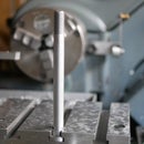
Step 4: Central Pillar


The beam Stirling engine is defined by a horizontal beam that connects the flywheel to the power piston. This beam needs to pivot about a point, which leads us on to the central pillar.
The pillar is first turned with a slight taper and polished. A slitting saw and drill bit are used to create a slit and pivot point for the beam. The hole is cross-drilled to 0.7 mm and will later be opened up using a tapered broach during assembly to ensure a good fit with a tapered pin.
To clear a reciprocating fitting, a region near the bottom of the pillar needs to be milled away. Perpendicular to this feature, a slot is milled for the rod which connects the flywheel and displacer to pass through later.
Finally, the component is reversed in the collet and a thread is cut in the base of the pillar.
Step 5: Bearing Housing


The bearing housing holds a pair of tiny 1.5mm ID ball races which support the flywheel. Using the same process as shown on the cylinder, two faces of the bearing housing are filed parallel. The hole for these bearings is cut using an endmill.
The top of the housing is filed round before separating it from the bar stock. Mounted the opposite way around in the collet, a thread is cut in the base of the part for mounting to the base plate.
The ball races are a snug press fit, pushed into place using a small vice.
Step 6: Hot Cap


The hot cap is the part to which heat is applied to drive the engine. It is important to maximise the temperature differential between the cylinder and this part, so stainless steel is an ideal material, thanks to its low thermal conductivity.
The thin wall of the hot cap is formed by drilling, then boring a hole in the stock. It is then parted off and reversed in the chuck to face off the closed end.
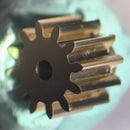
Step 7: Printing, Casting and Machining the Flywheel


It's certainly possible to skip most of these steps by opting for a simpler flywheel with flat spokes that can be machined but this seemed like a good opportunity to share the investment casting process.
First up, the flywheel is modelled in CAD. After some experimentation, we decided to add some solid support and a stub to the model at this stage rather than leaving the support up to the slicing software.
We have an Anycubic Photon resin printer, so we sliced the STL in Photon Workshop using the settings below. (You'll notice we printed two flywheels at the same time to have a spare.)
- Layer thickness: 0.05 mm
- Normal exposure time: 21 s
- Bottom exposure time: 80 s
- Bottom layers: 5
- Z lift speed: 0.5 mm/s
Once complete, the print is carefully removed from the bed, then washed and cured as you would for a normal print.
Using a soldering iron, several wax sprues are added to the model, which form a path for the molten metal to flow through during casting. The next step is mounting the model into a flask, into which investment slurry is added.
N.B. When using investment powder, always wear a suitable mask - the silica particles can cause serious lung damage if inhaled.
The powder and water are mixed together to form the slurry. The mixing process agitates the mixture, which inevitably introduces air bubbles. These can be removed by degassing the slurry in a vacuum chamber.
The mixture is then poured into the flask containing the 3D-printed flywheel and the flask is set aside for a couple of hours to let the slurry cure.
Once cured, the rubber flask base can be peeled off. The wax geometry is now surrounded by ceramic and can be melted out using a furnace. A starting temperature of 120°C is used, followed by a series of temperature ramps up to 730 °C, which melts the wax, then burns off any residue and fully cures the investment mixture.
The flask is removed from the furnace at around 650°C to pour the molten metal into what is now hopefully a flywheel-shaped cavity. The hot flask is placed over a hole in the vacuum chamber to help suck the metal into the mould cavity. In parallel, some brass is melted in a crucible using a blowtorch. When the brass is completely molten, it is poured into the top of the mould.
The flask and mould are quenched in water, which breaks up the mould and releases the casting. After checking the casting for defects, the excess material can be removed using a combination of hand tools, machining and milling. Leaving the central stub oversize provides a convenient surface for gripping the flywheel in the watchmakers' lathe.
Now that the flywheel is a more manageable size, it can be finished with some lighter cuts in the watchmakers' lathe and a 1.5 mm hole for the main shaft drilled in the centre.
Painting is of course optional too but the spokes of this flywheel were coloured using red enamel paint.
Step 8: Base Plate


All of the components need to fixed in place, so a base plate is made from a small piece of flat brass. The outer shape of this part isn't too important but the relative positions of the holes need to be precise. An easy way to get this right is using coordinate drilling with a DRO but manual measurement would be sufficient too.
Step 9: Con Rods, Beams and Pins


The con rods and beam are made from titanium shim, which is thin enough to be cut with scissors. The holes are drilled using a small high-speed drill and the corners are rounded with a needle file.
The beam and connecting rods are pinned in place with a 0.8 mm diameter tapered pins. These are made from short segments of piano wire. Each piece is faced off and deburred in the lathe, and a slight taper is applied using a diamond stone and burnisher.
A different approach was required for the pin connecting two con rods as there isn't enough metal to press fit a tapered pin here. This pin is cross-drilled with a 0.4 mm tapered pin which stops it from falling out.
Step 10: Crank


The crank comprises a brass ring with a radially threaded screw and a small pin. The pin is offset by 1.5 mm, which results in a piston stroke of 3 mm.
Step 11: Assembly and Testing


The three main components are mounted onto the baseplate first. The main pillar is threaded into the end of a pencil here but could be mounted using the same approach as the cylinder and bearing housing if preferred.
The crank is bolted onto the flywheel axle using a small screwdriver.
A dab of watch oil is used to lubricate the piston, which sits inside the cylinder. Next, the beam and connecting rods are fitted. The displacer is fitted into the other cylinder recess and the displacer con rod passes through the slot in the pillar.
The hot cap is a simple press-fit into the recess that was machined in the cylinder with the endmill.
Of course, the final step is testing if the engine runs over a small flame.
Thanks for reading!

Grand Prize in the
Big and Small Contest


67 Comments
2 months ago
did you see this one? https://www.youtube.com/watch?v=dAV_nWTwWR4 also very tiny and works with low temperature.
2 months ago on Introduction
Wonderful instructable, sir. At first I tought you were Chris from Clickspring youtube channel which has similar great machining skills. I also liked your watchmaker lathe. Congratulations and thanks for sharing.
2 months ago
Too cute! Hard to find appropriate words that haven't already been said. What are the chances of kits being made available in the near future? Would it help if I said please?
2 months ago
impressive project and beautiful design! congrats
3 months ago
Your work is awoesme and accurate :)
3 months ago
Your work is awoesme and accurate :)
3 months ago
Question: how long will the engine run? Do the fins dissipate enough heat to keep it running for a longer time, say 15-20 minutes?
Reply 3 months ago
It seems to run continuously. Because it's so small, it reaches steady-state quickly. I've only tested it with a lighter so far though, which is not designed to run continuously, so I haven't tried running the engine for this long.
Reply 3 months ago
I guess small size does help. I know that one of the problems with Stirlings is the need to dissipate heat from the cold side. Typically, the whole thing warms up and then won't run. Great machine work, BTW! And I especially like the rolling file guide!
Question 3 months ago on Introduction
A-MAZING!!
And the videography is SO good!!!
I have an idea I'd like to explore with you if you're interested....
Please contact me at JayPrab@BedfordControls.com.......
Answer 3 months ago
Thank you!
3 months ago
Superb craftsmanship and a detailed video. Congratulations
Reply 3 months ago
Thanks!
3 months ago
The stirling engines have always amazed me. I even bough some from the internet. Those that you put above a cup of hot water.
But yours is the best! I appreciate the long hours you spent!
Reply 3 months ago
Thank you! I have always been amazed by these incredible machines too.
3 months ago
Freakin' Amazing...
Reply 3 months ago
Thank you!
3 months ago
Genius!
Reply 3 months ago
Thanks!
3 months ago
Absolutely brilliant, I can't think of of anything else to say, I work with wood but obviously not on such a miniature scale, I was totally enthralled watching, thank you.