
Introduction: ESP32-Powered Tabletop Kinetic Sand Drawing Robot


In 2020, back when I had just started my sophomore year of high school, I built a very basic sand plotter robot that drew patterns in sand. Three years later, I wanted to use the skills that I have taught myself to revisit the design in order to be able to take it to college with me to Purdue in a couple of weeks! You can read more about the original robot here
The original inspiration came when I saw an Instagram ad for the SANDSARA Indiegogo campaign back in late 2019/early 2020.
This redesign has been in the making for the past six months. I recently wrote it up on my main blog here, however it was more of a showcase. I will attempt to explain in detail how to construct it, but feel free to leave a comment or contact me if you would like any more information :)
Supplies
3D Printer
ESP32 DevKit V1
2x TMC2208 -or- TMC2209 stepper drivers
2x mini nema 17 pancake steppers
2x hall effect endstop (generic ones will work fine)
TSL2561 light sensor
Panel mount USB-C and DC power jack
Custom PCB
4 inch lazy susan bearing
Assorted countersunk M3 screws
SK6812 RGBW led strip (1m) I used 144 leds/m
M3 heat set inserts (4.5mm OD)
Assorted 2,3,4,5 pin JST connectors and SMT sockets.
400MM GT2 timing belt w/ pulleys.
Step 1: Fusion 360


I designed this kinetic sand robot to be extremely slim, and with everything printed, it is under 3in tall! There are a lot of overlapping parts, mostly around where the large theta gear attaches to the base plate. The entire robot was designed from scratch in Fusion 360, and I've shared them online through Fusion Team (here)
Yes, Fusion 360 does say that this is version 55 of the mechanism... I spent longer than I want to admit during this phase of design :)
I started by sketching the rough shape of the enclosure, and then split it up along the large overhang to ensure printability. I then built the robot baseplate, modeled the lazy susan bearing, and the central gear stackup.
I've attached both a cutaway view and an exploded view of the robot assembly for more detail into how it goes together.
Step 2: 3D Printing!


I printed everything in black Polymaker ABS using 30-50% gyroid infill depending on the part. Usually, the internal components got 50%, and I just printed the enclosure with enough shells to make it solid. I'd estimate that I used almost all of the 3kgs of filament I bought for this project. I did a few printer upgrades during this project as well :p
PLA would've fared better in terms of less warping, however I wanted the structural properties of ABS.
I've attached a photo of me test-fitting the linear axis and it's guide rails.
Step 3: Robot Assembly


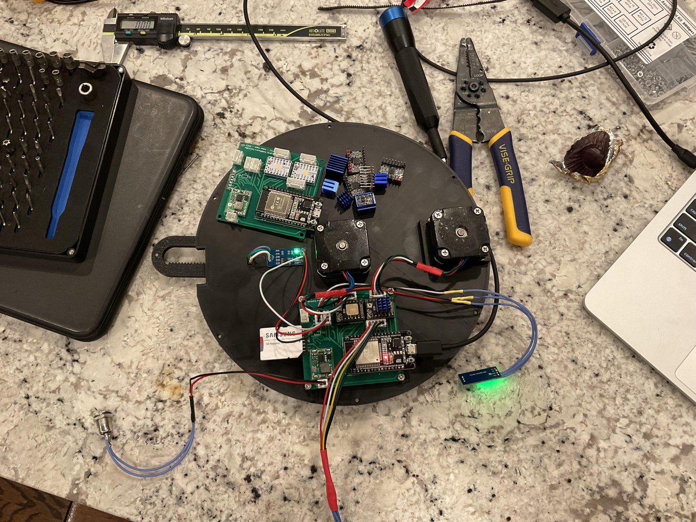
I added 4-pin JST connectors to the stepper motors, a 5-pin connector to the TSL2561 light sensor, and 3-pins to both magnetic endstops and the LED strip.
I then installed the theta stepper motor with countersunk M3 screws to the robot base plate. Then, I put the GT2 pulley on the motor, and screwed the lazy susan bearing into both the large central theta gear and the lower base plate using M3 screws. The bearing snaps right into place and shouldn't wobble. In the Fusion assembly, there is an optional spacer that can be used if it does. The linear axis and guide rails screws directly into the top of the theta gear with some heat-set inserts.
Step 4: PCB Design


I designed a very basic breakout board for all of the components using the standard version of EasyEDA and had it manufactured with a black soldermask.
I actually ended up changing the name to "Tranquil" when I was writing the web interface, I just never really wanted to re-order the boards just for some text.
The design is available here
Step 5: PCB Assembly


I simply soldered down the motor drivers, ESP32, and the JST connectors. I added an optional SD card slot that is compatible with MPN#47352-1001 (Mouser) I hand-soldered the connector with a fine point tip and some no-clean flux.
Step 6: Connect It All Up

I installed one of the magnetic endstop sensors right into the tiny hole offset from the center to sense when the theta gear arrived at a known position
The fully assembled robot base plate simply slides into the center of bottom half of the enclosure.
Step 7: Assemble Enclosure


Place top half of enclosure on bottom half. Screw down with heat set inserts & 12 10mm M3 screws.
Step 8: Add Sand

I took some generic craft felt I had at home and spray glued it to the bottom of the sand bed to make it super quiet. Then, I just dumped some Home Depot sand and spread it around with a butter knife.
Step 9: Lights! Camera? No, Just Lights..

I stuck the LED strip on the sides of the sand bed with some double sided foam tape, and ran the 3 wires (5V data and ground) through the tiny slit on the side, down to the main control board.
Step 10: Compiling the Web Interface


The web interface was written from scratch with a mix of TypeScript and Vue 3. State management is done with Pinia and data fetching is done with a set of Axios request interceptors.
The GitHub repository is here.
Simply clone and build the project to continue,
You can build the project on a *nix machine by running (change command for equivalent on Windows machine)
yarn && yarn build
Save the generated build files that are output in the ./dist directory.
Step 11: Compiling the Device Firmware

The firmware has been re-written from almost the ground up and has been in the works for at least a year now. It's a normal PlatformIO project and can be downloaded from here. Drag the built web assets to this directory and PlatformIO will automatically move them to the ESP32's SPIFFS partition.
The patterns featured are not provided and can be downloaded from the open internet. The web interface simply lists what patterns are installed on the device.
Step 12: Configuring Device
Once the firmware is installed, the device will setup it's own access point named "Tranquil" where all initial configuration is done. You can connect it to your Wi-Fi, setup OTA updates, and even (in my case) set it up as a WireGuard client. (see next step)
Step 13: Wireguard Client

You can go to the settings tab of the device and insert the relevant keypair and endpoint information for the robot to join a remote WireGuard subnet.
I make use of this as the college that I will be attending in the fall implements client isolation on their network, and without this, I would have no way to control the robot.
Step 14: Enjoy!


Thank you so much for reading! If you want to build your own, but are stuck somewhere, please let me know in the comments and I will definitely try my best to help!
I've now built two sand drawing robots and have gained so much experience in designing for printability and ensuring that the firmware that I write is stable!
You can see more of my projects on my blog: https://vigue.me, or follow me on GitHub @acvigue

Grand Prize in the
3D Printing Student Design Challenge


29 Comments
3 days ago
This is really a great work. Thanks for sharing. I am curious about how you restore the sand table every time you finish a painting. It seems that you have not seen the restoration device. I look forward to your reply
7 days ago
why the belt drive? If you are 3d printing stuff, why not print a simple gear? Just wondering. At some point in time I'm going to make something similar.
Reply 7 days ago
Just because it was quieter and had less play
Reply 7 days ago
thanks
10 days ago
Hi! Amazing project! A couple of questions I couldn't find from your instructions:
- you are using a 24V power supply, right?
- the second hall sensor sits on the upper half of the enclosure behind the motor with the belt?
I'm sure I'll have more questions further along. Thanks for the instructions!
Question 11 days ago
if I do a GET for "http://192.168.0.51/" it returns:
<!DOCTYPE html>
<head>
<meta charset="UTF-8">
<link rel="manifest" href="/manifest.webmanifest" />
<link rel="icon" type="image/png" href="/icon-192x192.png" />
<meta name="viewport" content="width=device-width, initial-scale=1.0">
<title>Tranquil</title>
<script type="module" crossorigin src="/assets/e7e8929e.js"></script>
<link rel="stylesheet" href="/assets/38748ddb.css">
</head>
<body>
<div id="app" class="w-full h-full"></div>
</body>
</html>
14 days ago
Very nice. I was expecting to see a slip ring to keep the wires for getting twisted. Is it not listed in the article or was some other solution used?
Reply 14 days ago
No wires go through the center
Question 23 days ago
would this work with a HUZZAH32 – ESP32 Feather Board?, when i upload it to the feather it seems to run but when I go to 8.8.4.4 to setup the wifi credentials, the page doesn't exist(too many redirects)
Answer 23 days ago
Did you compile and upload the web interface to the device using PIO sidebar -> Upload Filesystem.
Reply 23 days ago
getting the same result,
ive ordered the same board you used anyway but
I build TranquilVue, put all the files from "dist" output into a folder at the root of TranquilFirmware called "data", upload filesystem, upload.
I've tried the other way upload, upload filesystem, same results
seems to be uploading both fine, is there something im doing wrong?
upload filesystem image log:
pastebin.com/jzf9gPiq
upload log:
pastebin.com/WXdraRgb
serial monitor:
pastebin.com/vRVpLDYm
Reply 22 days ago
I can take a look at it later today, it's most likely due to the SD card not being present. It's supposed to be optional but unfortunately in some places it is hard coded.
Reply 15 days ago
Hey,
Did you get a chance to go through the issue?
The webpage does not open, too may redirects.
Reply 21 days ago
I tried the same on an ESP32 DEVKIT V1 and I was getting the same result, must be something to do with the SD card as you mentioned
18 days ago
This is sick!
Question 19 days ago
The single and MOST important part is the “BALL”. It is what the viewer sees moving.
I looked pretty thoroughly through the Instructable and could not find the “BALL” part.
I am very unhappy that without the size and material of this part I will not be able to make the Instructable as shown. I feel sad and stupid at the same time.
Answer 18 days ago
i also noticed he made no mention of where how to embed magnets to actually control the ball.. i would love to attempt to make this project but the instructable seems very vague and lacks a LOT of detail for someone like me who has no idea how to code firmware etc on something like this.. disssapointed for sure
Reply 18 days ago
me personally i designed a little magnet holder with an m3 bolt hole at the bottom to attach it to a nut on the underside of the overhang, he has kindly given access to the fusion360 files so you could use them as a nice base, I also changed how I attached the gear to the bearing as I don't have any inserts, so I use a nut slot.
hope this helps
Reply 18 days ago
The magnets are shown on both the exploded diagram and the cutaway view. This instructable is not meant as a first project if you don't understand how to program.
Answer 18 days ago
It's a standard metal ball. The size is up to the user. This project has taken many months to put together and as such, I have forgotten to include some parts.