
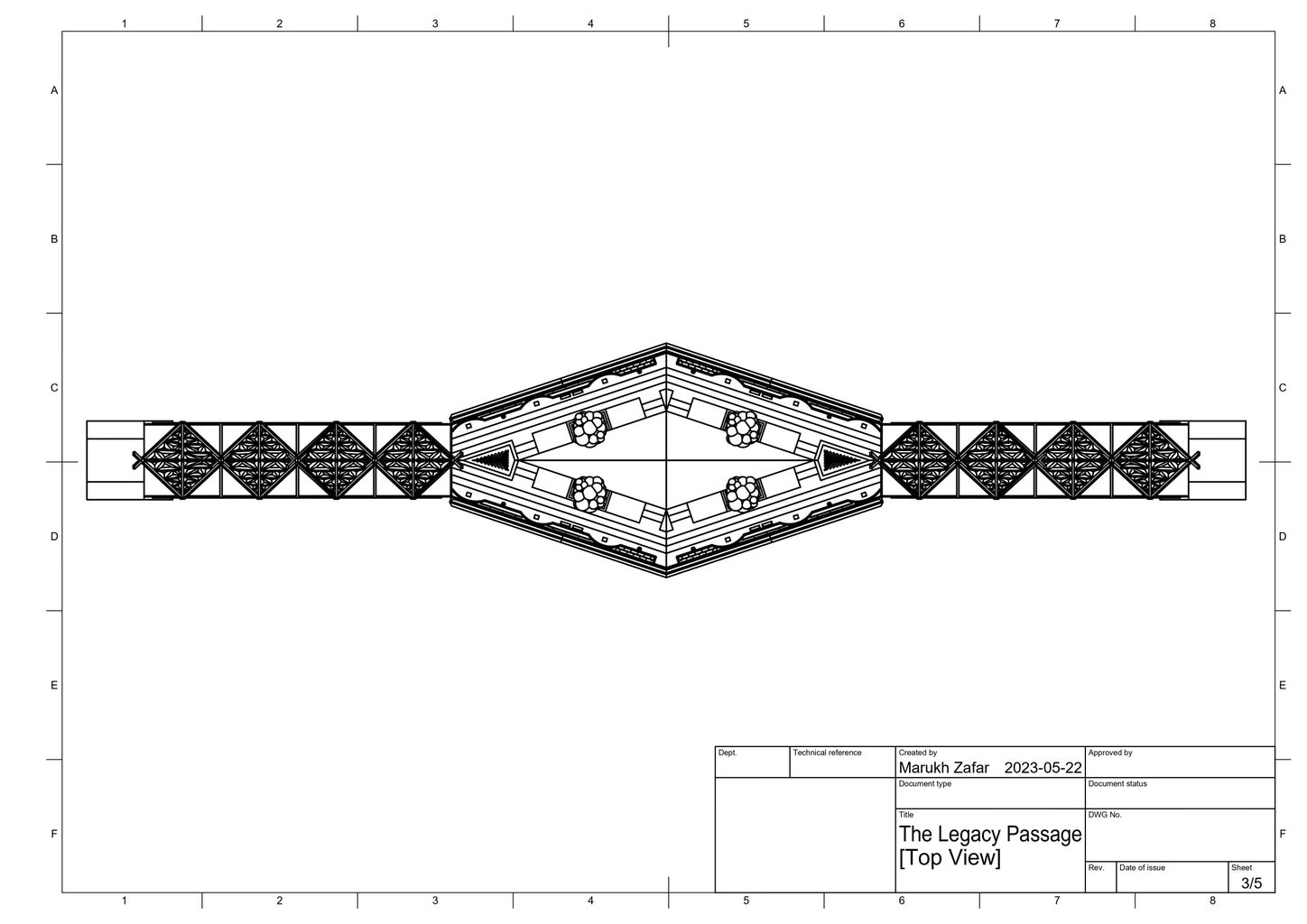
Introduction: The Legacy Passage: Honoring Heritage and Healing Through Truth and Reconciliation


Hi, my name is Marukh Zafar! I am a seventeen year old grade 12 student from Nelson Mandela High School in Calgary, Alberta. My school offers a Robotics course and this is where I got to explore the realm of 3D design; I am fascinated by the power of computer-aided design (CAD) software and the ability to transform concepts into intricate, three-dimensional models. My interest in engineering stems from a deep curiosity about how things work and a desire to make a positive impact on society. I am particularly drawn to the field of 3D design, where I can apply my technical skills and creativity to bring ideas to life in a virtual environment. This fall, I will be entering the Schulich School of Engineering at the University of Calgary to pursue civil engineering.
What stuck out to me the most about the Make it Bridge Challenge was how it requires contestants to build both not only a physical bridge to improve accessibility, but also a metaphorical bridge to strengthen the connections between people. I believe that every piece of infrastructure must serve a technical purpose to heighten efficiency or quality of life; but it must also serve a civic purpose of creating a sense of belonging across lines of difference.
Being a Canadian, I inherit this nation's devasting history with Indigenous cultural genocide. Canada has a dark past when it comes to the first nations; it is embedded with tales of white supremacy and assimilation. Early settlers stole indigenous land forcing natives onto tight reserves to make way for trading posts and farms. For a large part of the 19th and 20th centuries, natives were seen as second-class citizens that needed to be integrated into mainstream society. Specifically, 150,000 First Nation, Inuit and Metis (FNMI) children were forced to attend schools operated by churches in an attempt to assimilate them. The scars of colonialism can still be seen in these people today, and its toxins will only accumulate if we do not attempt to dilute them.
With this in mind, I wanted to combine two ideas that I was very passionate and felt strongly about: engineering and the indigenous people of Canada. I wanted to create a bridge that honoured and celebrated native culture, while at the same time acknowledging the atrocious crimes committed against native families in the past. This bridge is to be a step forward in asserting our responsibility as Canadians in rekindling our relationship with the native people of our country.
Supplies


- Computer set-up or laptop
- It is preferred to have a graphics card since it will take longer for programs to run solely on computing power, especially when rendering
- Fusion 360
Step 1: Picking a Location: (1) Accessibility


The location of a bridge significantly influences its design considering the terrain, hydrology, traffic needs, environmental impacts, social context, and connectivity requirements.
What was most important to me were accessibility and social/cultural factors.
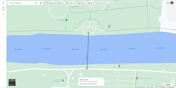
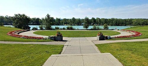
In regards to accessibility, Baker park and Bowness Park see hundreds of visitors each day. Baker Park is known for its disc golf course, amphitheater, promenades, and river observation point. Right across Baker Park is Bowness Park, one of Calgary's most popular parks. Its highly used for picnicking and paddle boarding in the summer and ice skating in the winter. It would make sense that both if these parks would have some kind of bridge connecting them, allowing citizens to easily go across from one place to the other. But, there was no direct passage available that allowed pedestrians to travel from Baker Park to Bowness Park. There were bridges on either ends that crossed over the Bow River, but this makes the journey around 1.5 - 2 km. Moreover, these bridges focus on transportation for vehicular traffic, with only a small skinny pathway on the side of the flowing traffic, which is unsafe for pedestrians.
Having a bridge that directly carries across from one park to the other decreases the travel for pedestrians by 90.3-92.7%, shrinking the journey to only 146 m. This bridge would make travel between the two bridges much more efficient, safe, and enjoyable, allowing pedestrians to access and travel more freely between the two areas.
Not only would this make the parks more accessible to communities on either side of the river, but it would also help the communities connect with one another. The Bowness, Greenwood, Silver Springs, Scenic Acres, and Tuscany communities are all located on either side of the Bow River. Building a bridge here would help foster a sense of unity and cooperation while also creating a more inclusive society where people from different backgrounds can interact, understand each other's perspectives, and work together for common goals.
Step 2: Picking a Location: (2) Land Significance
In the previous step, I outlined how I chose to connect Baker and Bowness park with a bridge to enhance accessibility for the communities around. But, I could have chosen any communities separated by a body of water as a location for my bridge. But, I specifically chose it between Baker Park and Bowness Park because of the area's historical significance to the indigenous. The Bowness area was initially inhabited by various nations from the treaty 7 region of Alberta: the Blackfoot, Stoney Nakoda, Cree, and Tsuu T'ina people. These tribes saw the value of the land and took on a diligent duty to nurture and protect it; they relied on it for hunting and gathering because of the fertile pastures and wild buffalo herds.
We all know where the story goes from here.
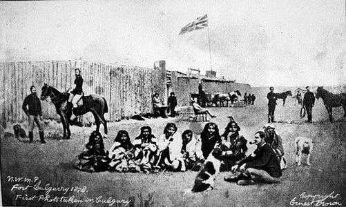
European settlers arrived and took advantage of the land and the native people, leading to the establishment of a Hudson’s Bay Trading Post: Fort Calgary. As a result, indigenous people were forced to sign treaties they did not understand and did not agree to and consequently, they were stripped of their land and pushed to the fringes on reserves. To this day, Calgary has still struggled to come to terms with the history of the Bowness community.
With that said, right across from Bowness Park lies Baker Park. The namesake of this park comes from Dr. Albert Henry Baker who was the director of Baker Center Tuberculosis Institution, a tuberculosis sanitorium that was once on the same land as Baker Park. Tuberculosis sanatoriums have a dark history with native people. Today, many indigenous victims are speaking out about how they were detained at these institutions and forced to undergo surgeries. A lot of the procedures that these victims underwent were done "without merit and without consent". Specifically, some indigenous children were brought to sanatoriums without parental consent because funding was tied to quotas. Now, doctors say that many indigenous sanitorium survivors were experimented on.
I find it astounding that Baker Park and Bowness Park shared such a devastating history. But, before I had done my research, I was not aware of any of this. I did not even think that my City of Calgary had a place in these events. These were parks that I had visited in my childhood and still visit today; I was ashamed that I did not know that this land was stolen from native tribes and that it unethically experimented on native people in the past.
This ultimately was the defining factor in deciding the location for my bridge. Although accessibility was also important, I wanted to link Baker and Bowness Park together because of their common history. I wanted to recognize our past mistakes by a bridge project that was built under the purpose of acknowledging these historical atrocities. But, at the same time, I wanted to create something beautiful that celebrated the richness and uniqueness of the native community after years and years of assimilation.
It was time to get designing!
Step 3: Finding a Vision: Exploring Symbols for the Bridge Shape
Initially, I was a little lost when I first pulled out the drawing board. I did not know where to start!
I decided I needed something to give me inspiration for the basic shape of my bridge; the hard part was that I wanted the shape of my bridge to connect to the indigenous as well. I scoured the internet for numerous native american symbols.
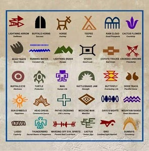
Buffalo Eye: The buffalo eye was an interesting one because this animal is of immense important to Native people, there is even a national memorial in Alberta called Head-Smashed-In Buffalo Jump. Historically, buffalo were a primary source of sustenance for many Native communities. They provided meat, hides for clothing and shelter, bones for tools, and other essential resources that contributed to their survival. The sustainable hunting and management of buffalo herds have long been part of native environmental stewardship practices, ensuring the long-term survival of the species. I coul dhave incorporated the buffalo eye symbol into my bridge as a central garden.
Sun: The sun is a powerful representation of life and vitality. It provides warmth, light, and energy, essential for the growth of crops, sustenance of wildlife, and the overall well-being of all living beings. The rising and setting of the sun each day symbolize renewal and the cyclical nature of life. It represents the idea of new beginnings and the hope for a better tomorrow. I beleived that this concept would make a sun an interesting inspiration for the shape of the bridge. I could incorporate patterns on the external side and ray-like walkways that extend from a central garden.
Seasons: The seasons symbol is a diamond-like shape that I could easily incorporate into the shape of my design. The reverence for the seasons is a fundamental aspect of Native American cultural identity. The acknowledgment and celebration of seasonal changes are a way of preserving and perpetuating their heritage.
None of these symbols really touched my heart; the buffalo eye was one that showed promise, but I wanted something that shared a strong connection with the significance and purpose of my bridge.
Step 4: The Design: Eureka! the Medicine Man!

The reason I spent so much time on the shape of my bridge was because it would ultimately define the flow of the people using it and how the surrounding nature would weave around it.
I eventually came across the medicine man symbol.
- Healing and Well-being: The primary role of the medicine man is to facilitate healing and promote well-being within the community.
- Spiritual Guidance: Medicine men are seen as spiritual leaders who act as intermediaries between the human world and the spirit realm; they communicate with ancestors, spirits, and deities to seek guidance, protection, and blessings for the community.
- Problem Solving and Conflict Resolution: In addition to healing, medicine men are often sought for problem-solving and conflict resolution. They offer spiritual and emotional support through their insight and advice to individuals or the community as a whole.
- Connection to Ancestors: The medicine man's role in communicating with ancestors fosters a deep connection to the past and ancestral heritage and this connection is essential for maintaining cultural continuity and honoring the wisdom of past generations.
- Sustainable Relationship with Nature: Medicine men often hold a profound understanding of the natural world and the interdependence of all living beings. Their teachings emphasize sustainable practices and respect for nature, guiding the community towards ecological harmony.
- Protection and Blessings: Medicine men are believed to possess spiritual powers that can protect the community from negative influences, such as malevolent spirits or illness. They perform rituals to bless individuals, events, or important endeavors.
This was perfect! My bridge was meant to help heal the historical scars inflicted on indigenous cultures by our past misdoings. The very purpose of the medicine man was to heal! I found it so poetic and so powerful if my bridge was based off of this symbol: imagine Calgarians weaving through the shape of the medicine man symbol as they cross a bridge that is defined on the purpose of healing and understanding one another. Moreover, the medicine man also had powers of protection, which was also an important concept in my bridge. Part of what I wanted to do with my project was to educate people on the history of indigenous in Canada; I believed that this was of utmost importance to ensure that history does not repeat itself. This is how we protect ourselves from the influences of the past, and the duty of the medicine man is to protect the community from negativity or hardship. Additionally, the medicine man helps in maintaining a connection with previous ancestors. Ancestral heritage is an important part of my project; it is vital that we acknowledge the difficulties and discrimination faced by historical native figures of the past and my bridge will do this through informative pedestals that honour inspirational native figures and their accomplishments. Finally, the medicine man also plays a role in conflict resolution, which again, touches the very heart of my design and purpose. In the past, many native tribes were tricked into signing off their land, giving European settlers the legality they needed to push them off to fringes on reserves were they often starved or killed. The medicine man symbol is based on solving conflict; on understanding previous mistakes and starting anew.
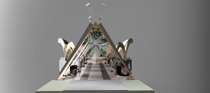
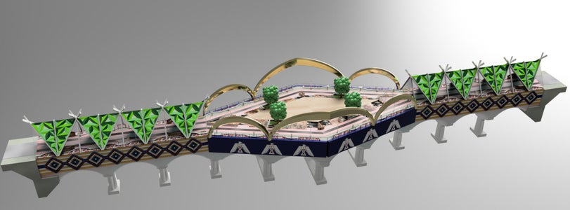
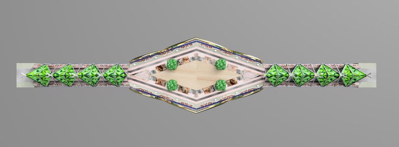
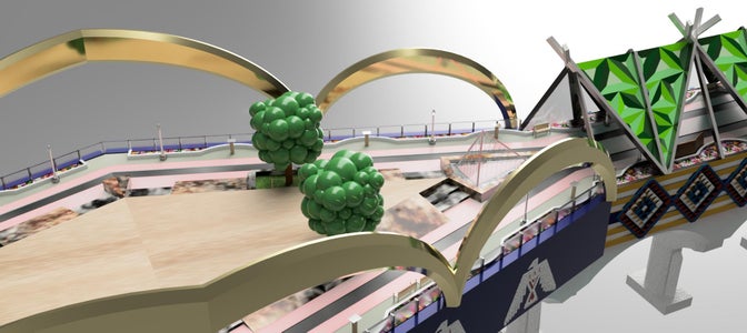
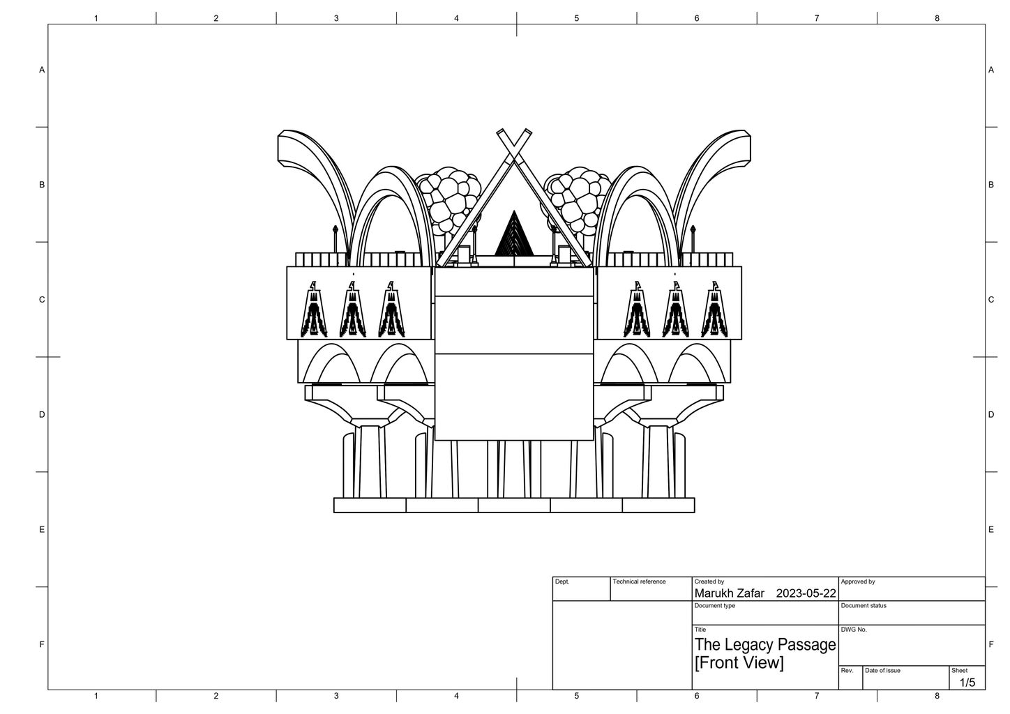
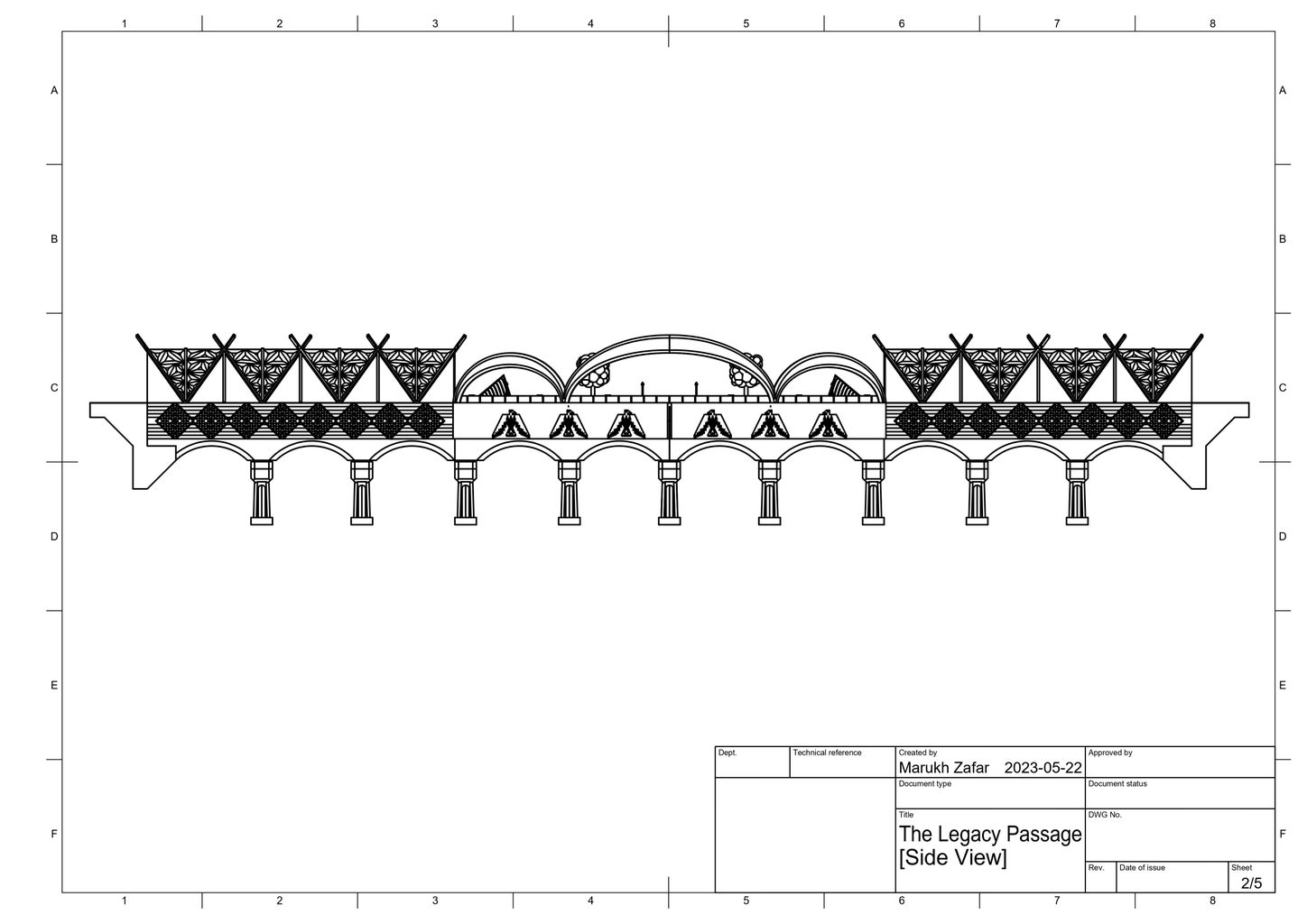
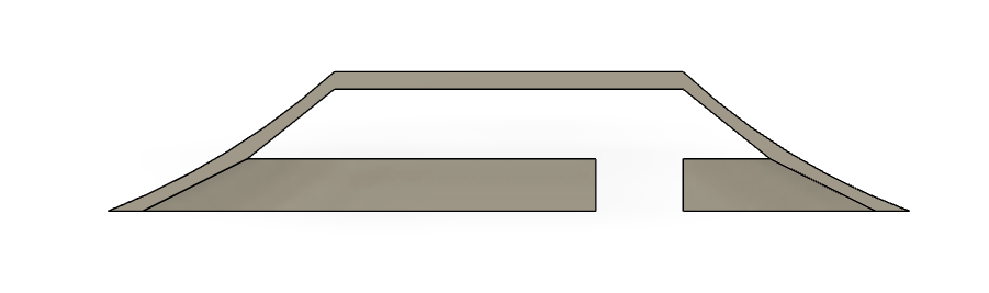
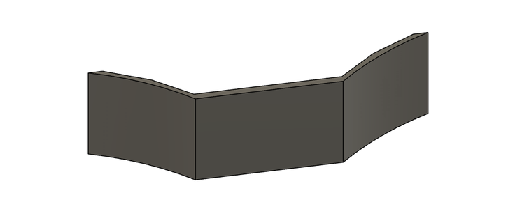
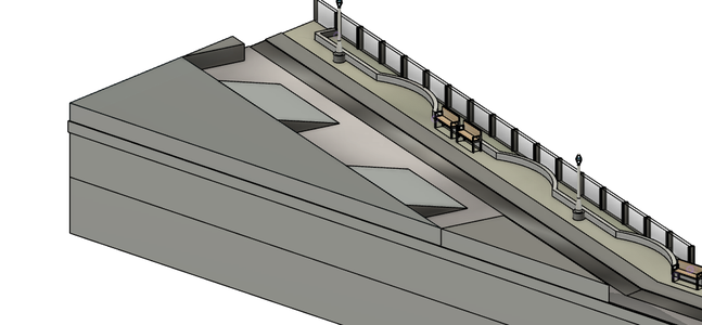
In the end, I decided that my bridge would be made up of two walkways that carry towards a central stage in the shape of the medicine man symbol. I find it so powerful and dynamic to have people walking on either end of the bridge towards the medicine man, towards healing, protection and conflict resolution.
Step 5: Planning
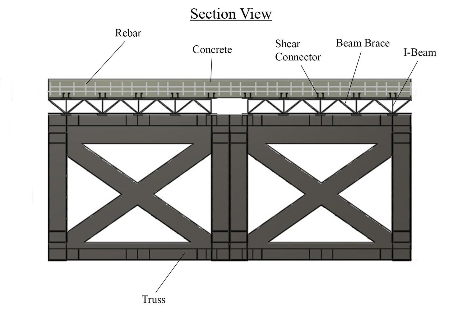
Deck: The deck is going to be constructed from I-beams, beam braces, shear connectors, and concrete.
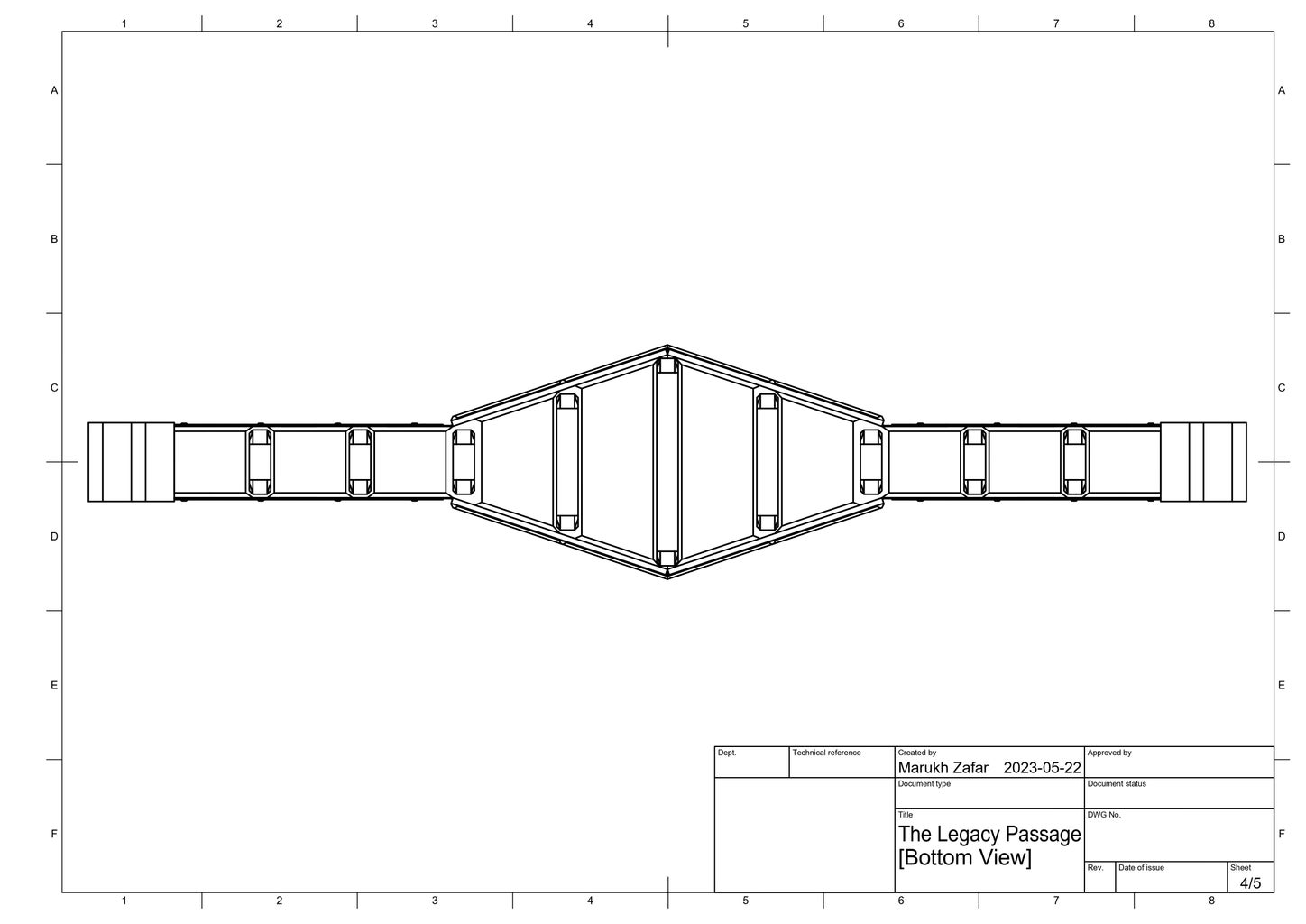
Truss: This bridge is going to be a deck truss bridge, meaning the truss is below the deck. Moreover, I will be utilizing the Howe truss.
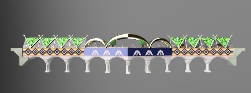
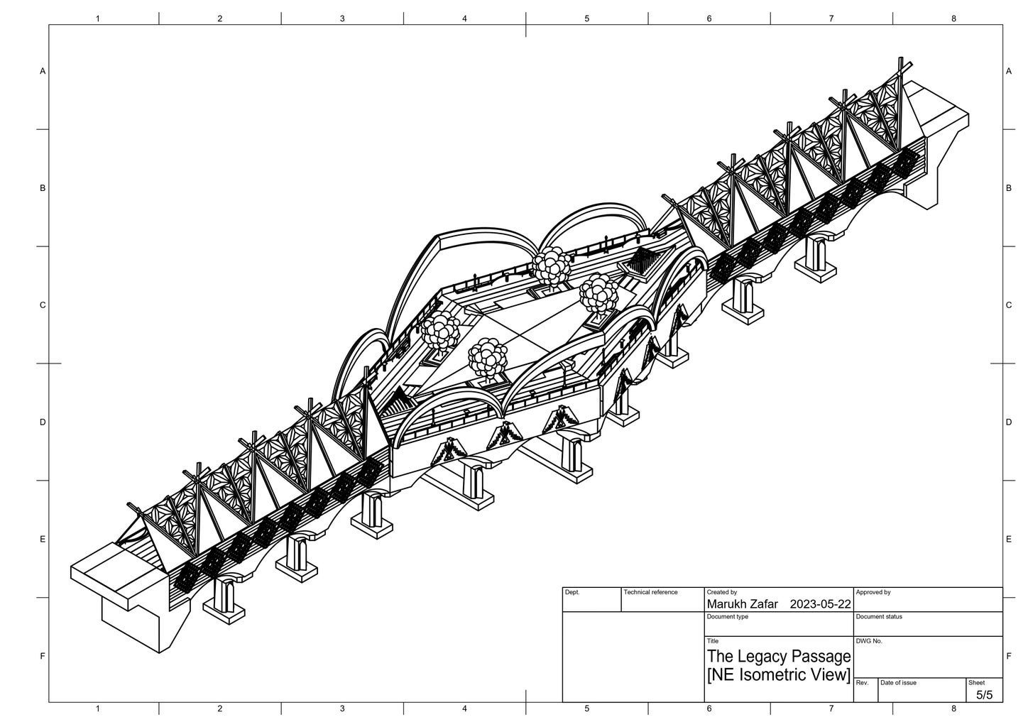
Arches: Above every set of piers, there will be arches. Arches distribute loads along their curve, which mimics the natural compression found in many natural structures like caves and rock formations.
Bridge bearings: Bearings made of rubber and aluminum are going to be placed between the truss and the piers; the rubber disc in the center of the bearing allows for some flexibility and movement to help account for thermal expansion. There are going to be 13 piers, so the design will need 26 bearings in total, 2 for each pier.
Piers: Since the bridge spans a larger distance, around 146 m, it is going to need piers. I decided on 13 piers so they can be evenly spaced throughout the entire length of the bridge. Since the center of the bridge is going to be larger, and therefore heavier, it will be carried by more beams compared to the walkways.
Foundation Blocks: This is probably the most necessary part of the design as it provides the bridge with a stable sitting, ensuring its longevity as a secure structure.
Cutwaters: The cutwaters provide some flood control and will be incorporated into the pier.
Tunnel: Rather than having a completely open bridge, the tunnel provides a sheltering space that can protect pedestrians from harsh weather. The mosaic will be made from Plexiglas and supported by an aluminum frame of warren truss members with verticals.
Abutments: On either side of the birdge, their will be abutments, or masses of reinforced concrete, that help anchor the bridge to the land separated by the Bow River.
3-sisters: The three sisters are an important native American concept and it refers to three very important crops: corn, beans, and squash. These crops are symbols of resilience and balance and I wanted to include them in my bridge. There will be three aluminum arches carrying across center portion of the bridge, each from one crop.
Stage: The potlatch is an important native festival and celebration that was institutionally banned in the past in an attempt to assimilate indigenous people. There will a stage in the center of my bridge dedicated towards indigenous potlatches, dances, and art exhibitions.
Railing: Only the larger portion of the bridge will need a railing because the walkways will be protected by the tunnel.
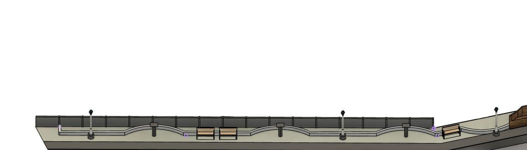
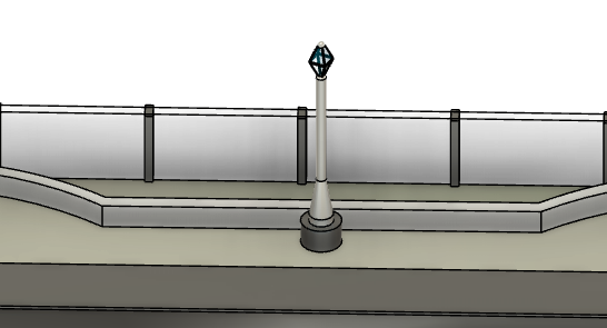
Streetlights: To create a sense of security and safety, streetlight will be implemented throughout the length of the bridge.
Designs: The outer side of the bridge will incorporate rich native art in the form of geometric patterns and symbols; this is one of the ways I plan to use my project to celebrate native American art and culture.
Garden: Surrounding the walkways will be a series of gardens with various flora and fauna picked out based on indigenous significance.
Fountain: On either end of the stage, the bridge will have a water fountain. Rather than the traditional fountain, it will be designed in a more skeletal and geometric fashion.
Pedestals and information boards: Throughout the length of the bridge, there will be a series of information boards and pedestals. These structures will provide pedestrians with information on previous acts committed against native American people, while also celebrated certain native American figures and their accomplishments.
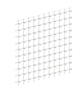
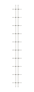
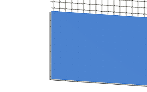
Step 6: Rebar Reinforcements: (1) Horizontal Rebar

Purpose: The bridge is going to have a concrete base, but it must be considered that although concrete is strong in compression, it is relatively weak in tension. The addition of rebar significantly enhances the tensile strength of concrete structures. Moreover, concrete is susceptible to cracking due to shrinkage, temperature fluctuations, and applied loads. Rebar helps control and prevent the formation and propagation of cracks in concrete structures. By providing reinforcement, rebar limits the width and extent of cracks, enhancing the durability and longevity of the concrete.
How-to: Extrude a 0.5 long cylinder with a 2 cm diameter horizontally across the x-axis. Then, use the rectangular pattern tool to duplicate this component along a linear axis; the quantity should be 10 and the spacing between each rebar should be 18 inches.
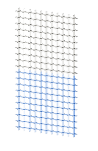
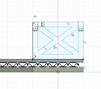
Step 7: Rebar Reinforcements: (2) Vertical Rebar

Purpose: In this project the rebar spacing will be 18 inches. 18 inches is a relatively smaller grid spacing given the vast area of the project, however, smaller grid spacing offers better resistance against shear forces and torsional stresses, making the structure more stable and capable of withstanding lateral loads and dynamic forces. Tighter spacing of rebar enhances the durability of the concrete by minimizing the potential for corrosion and degradation. It helps to prevent water penetration and the ingress of harmful substances, such as chlorides or sulfates, which can damage the concrete and corrode the reinforcement.
How-to: Similar to the previous step, extrude a 0.5 m long cylinder with a 2 cm diameter, but this time vertically across the y-axis. Then, use the rectangular pattern tool to duplicate this component along a linear axis; the quantity should be 11 and the spacing between each rebar should be 18 inches.
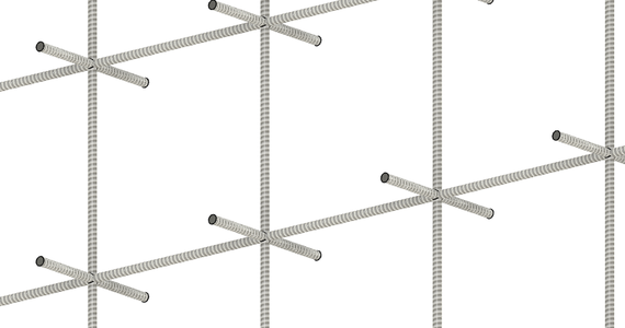
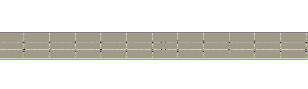
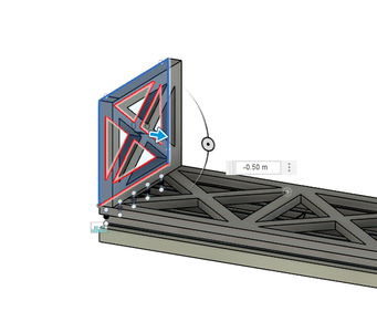
Step 8: Rebar Reinforcements: (3) Intersection Rebar

Purpose: In order to add more stability and structure to the concrete, I also added rebar to each intersection between the vertical and horizontal rebars as this further strengthens the concrete footings by preventing shifts due to temperature and humidity.
In total, there will be rebars in three directions: x, y, and z. Although it may seem that welding these rebars together at their intersections may provide better durability, I decided it would be better to use steel rebar ties using the figure-eight tie, which is the strongest of rebar ties. Calgary often sees sudden changes in temperature, with frigid winters and scorching summers, and this becomes a problem for welded rebar in concrete. Welded joints in rebar can introduce stress concentrations and potential weak points in the structure. This is because rebar and concrete have different contraction and expansion rates, which can cause concrete to crack as it creates pressure points. Additionally, the high temperatures involved in welding can alter the microstructure of the steel, making it more brittle and susceptible to failure.
How-to: At either side of each intersection, extruded a cylinder with a 2 cm diameter, one with a length of 7.5 cm and on the other side, one with a length of 13 cm. Then, use the rectangular pattern tool to duplicate these components; along the x-axis, the quantity should be 11 and the spacing between each rebar should be 18 inches, and along the y-axis, the quantity should be 10 and the spacing between each rebar should be 18 inches.
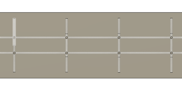
Step 9: Rebar Reinforcements: (4) Threading the Rebar
Purpose: The threads on threaded rebar provide a higher surface area for adhesion between the concrete and the rebar; specfically, a threaded profile allows for a greater mechanical interlock between the concrete and the rebar, reducing the likelihood of shear failure.
How-to: Give each rebar a 20.00 mm GOST self-tapping screw thread.
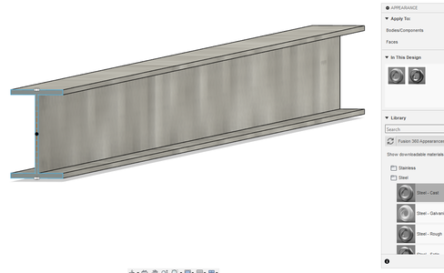
Step 10: Rebar Reinforcements: (5) Applying Galvanized Steel Apearance
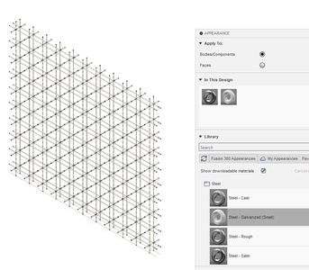
Purpose: Steel is often used for rebar because its thermal expansion coefficient is very similar to that of concrete. This design will use galvanized steel; a zinc coating acts as a barrier between the steel and its environment, protecting it from corrosion caused by moisture, humidity, chemicals, and other corrosive substances. As a result, galvanized steel has an extended lifespan compared to untreated steel.
How-to: Change the appearance of the rebar to galvanized steel.
Step 11: Rebar Reinforcements: (6) Layering the Rebar
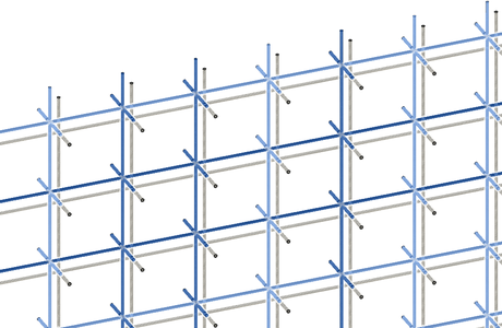
Purpose: The general rule is that rebar is needed for concrete that is more than 5 inches deep. Therefore, I decided to have two layers of rebar that were separated by 13 cm to further strengthen the build and security of the concrete.
How-to: I mirrored the entire structure using the circular face of one of the intersection rebars as a mirror plane.
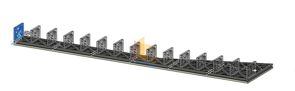
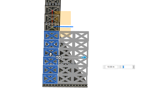
Step 12: Rebar Reinforcements: (7) Laying the Rebar
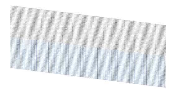

Purpose: The current area of rebar created will not be large enough to host the size of the bridge sector. So, it needs to duplicated along the circular faces on the sides.
How-to: The rebar needs to be laid side by side. Select everything and use the mirror tool to duplicate the rebar using one of the circular faces from the vertically or horizontally laid rebar; do not use the face from the shorter intersection bars. Continuously lay rebar using the mirror tool until the rebar forms a rectangle with a width of at least 73 m and a length of at least 20 m.
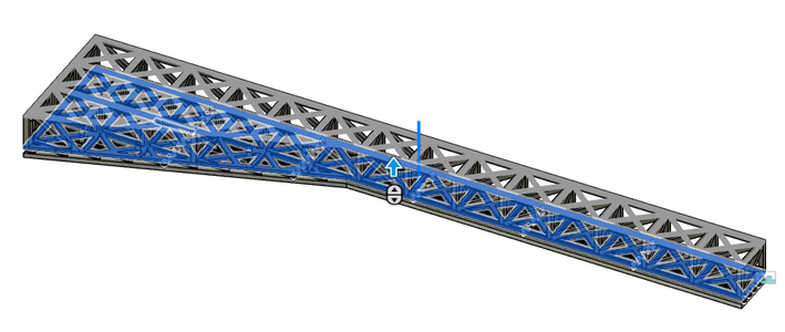
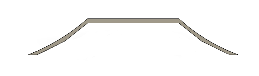
Step 13: Rebar Reinforcements: (8) Defining the Shape of the Bridge
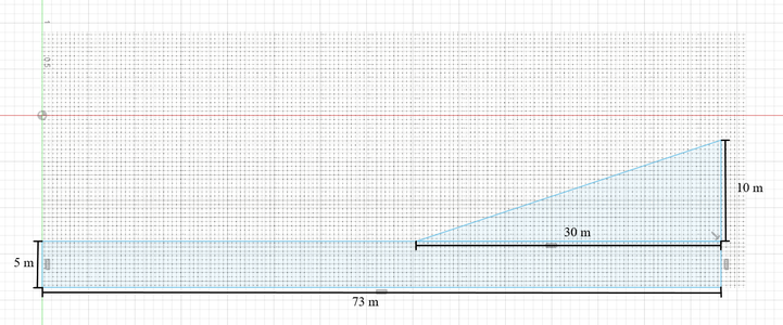
Purpose: When deciding the shape of the bridge, I wanted to design something unique rather than a bridge that would go straight across. Specifically, the Michael S. Van Leesten Memorial Bridge provided lots of inspiration; it was different from other pedestrian bridges in that it was both wider and had a longer span. At its widest part, it was around 25 m across; the wide-open area served as a relaxing community space.
The main design for my bridge is based on "the eye of the medicine man", a Native American symbol. A medicine man was believed to have powers of spiritual healing and seeing into the future. I believed that this would be an appropriate symbol for the shape of my bridge as its purpose is founded upon healing our relationship with the first nations, upon looking towards a future where we better understand the beauties of each others’ cultures and traditions.
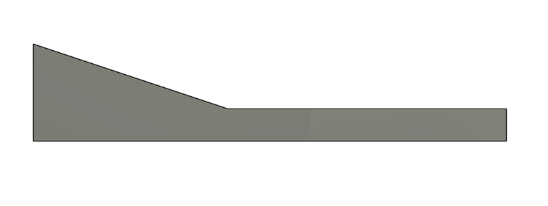
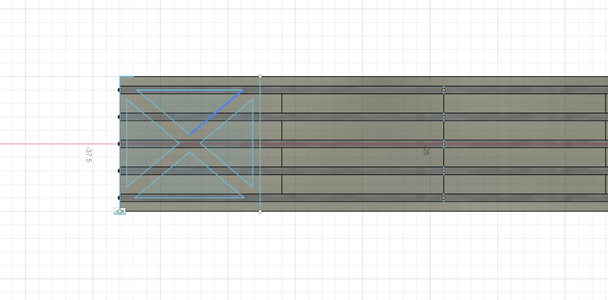
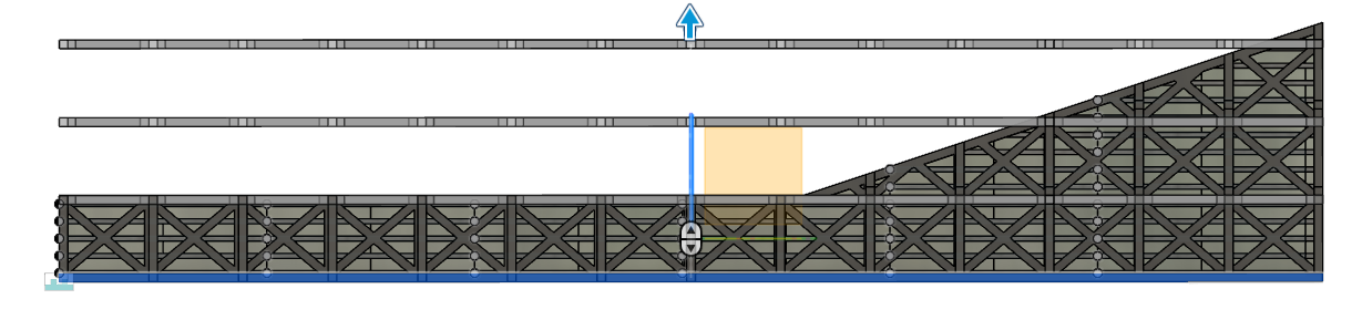
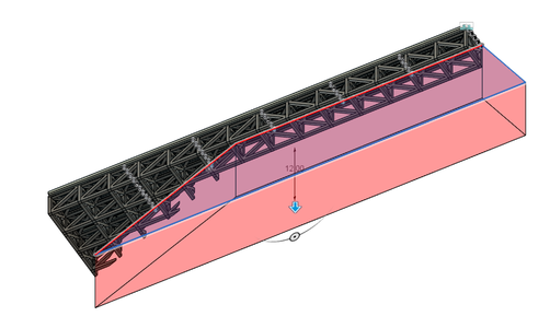
How-to: Start a new sketch, using a circular face from the intersection rebar as a sketch place. Create a rectangle with a width of 73 m and length of 5 m. Then, from one edge of the rectangle, draw a right angle triangle with a base of 30 m and a height of 10 m.
*Symmetry is going to be a big part of this project. Rather than creating the entire bridge at once, I will start by building a quarter, and then mirroring it four times at the very end.
Construction:
- Cutting and Bending Rebar: Steel bars will be delivered to the construction site in straight lengths where workers will use cutting tools to cut the rebar to the required lengths according to the project's specifications; the rebar is then bent to the appropriate shape using rebar benders or manual bending techniques.
- Placement of Rebar: Once the rebar is cut and bent, it is placed inside the formwork or molds, which define the shape of the concrete element. The rebar is positioned according to the engineering design, ensuring it is adequately spaced and aligned to provide optimal reinforcement.
- Tying Rebar: After the rebar is placed, workers use tie wires to secure the intersecting points of the rebar to maintain their positions within the formwork. This tying process ensures that the rebar stays in the correct position when concrete is poured.
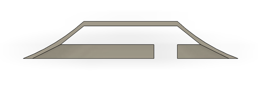
Step 14: Concrete Deck: (1) Adding Concrete to the Rebar
How-to: Extrude the previous shape by snapping it to the circular face of the intersection rebar on the opposite side of the sketch.
Then, select one of the large faces of the bridge and outline it using the line tool; extrude it once again by 5.5 cm and repeat this on the opposite face. This was done to embed the intersection rebars in concrete.
Step 15: Concrete Deck: (2) Removing Extra Rebar and Adding Concrete Appearance
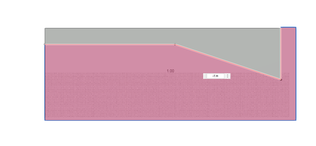
Purpose: When laying the rebar, the area was made larger than the actual size of the bridge to compensate for the jutting side of the sector. Now, the extra rebar that is still exposed needs to be removed.
How-to: Use one of the large faces of the bridge as a sketch plane. Use the line tool to outline a large shape enclosing any extra rebar that did not make it into the concrete. Then, extrude the enclosure by -1 m, ensuring that the extrusion is on the cut operation.
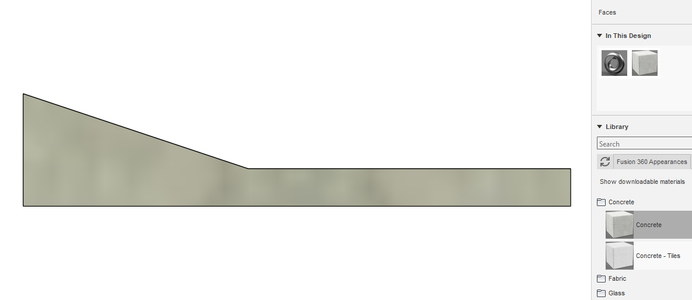
Change the appearance to concrete.
Construction:
- Concrete Pouring: With the rebar in place and secured, the concrete is poured into the formwork. The concrete flows around and encapsulates the rebar, forming a composite material that benefits from the tensile strength of the steel and the compressive strength of the concrete.
- Consolidation and Finishing: During the pouring process, workers use vibrators to eliminate air pockets and ensure that the concrete fills the formwork uniformly. After pouring, the surface of the concrete is finished and smoothened as required for the specific application.
- Curing: Once the concrete is poured, it needs to cure to achieve its full strength and durability. Curing involves keeping the concrete moist and at the appropriate temperature for a specified period, usually a few days.
Step 16: Beams and Shear Connectors: (1) Creating an I-beam
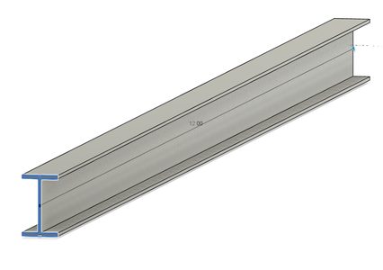
Purpose: I-beams are commonly used in bridge construction to provide support and strength to the concrete deck. They resist bending, shear forces, and torsion, which helps maintain the overall stability of the bridge structure. Moreover, bridges often need to span long distances without intermediate supports. I-beams have a high strength-to-weight ratio, allowing for longer spans with fewer supports. This reduces the number of piers or columns required, enabling the construction of longer and more efficient bridges.
Beneath the section of the concrete, there will be 5 W 18 x 119 I-beams spaced 1 m apart.
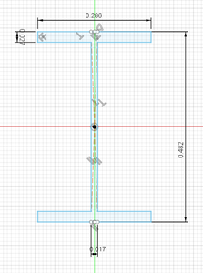
How-to: Create a new drawing for the I-beam; it is going to be made from 3 rectangles. Start with a center rectangle with a width of 0.0166 m and a length of 0.482 m. At both ends, center a rectangle with a length of 0.0269 m and a width of 0.286 m.
Then extrude the shape by 12 m and change the appearance to steel-cast.
*I-beam dimensions are often recorded using the American imperial system, however, since I am Canadian, I converted all units to the metric system.
I have included the original dimensions from EngineeringEdge below:
d = 18.97 in
bf = 11.265 in
tf = 1.06 in
tw = 0.655 in
Step 17: Beams and Shear Connectors: (2) Creating a Shear Connector
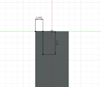
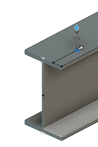

Purpose: By welding shear connectors to the top flanges of the I-beams, a composite action is achieved between the steel beams and the concrete deck. The connectors prevent the relative movement between the steel beams and the concrete, ensuring that they act as a single unit when subjected to loads; this composite behavior enhances the load-carrying capacity and reduces deflection of the bridge. Furthermore, the welded shear connectors effectively transfer the shear forces between the steel beams and the concrete, allowing them to act together as a composite structure. This load transfer mechanism increases the overall strength and stiffness of the bridge.
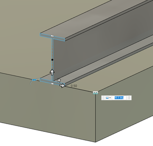
How-to: For this design, the SC12-075-11 stud will be used. Select the flange of the I-beam as a sketch plane. Starting from any corner, find a point that is 0.065 m left/right and 0.2 m up/down. Start by extruding a cylinder with a diameter of 0.019 m and a length of 0.12 m. Then select the circular face of the cylinder as a sketch plane and extrude a cylinder with a diameter of 0.032 m and a length of -0.0095 m, make sure the extrusion is on the join operation.
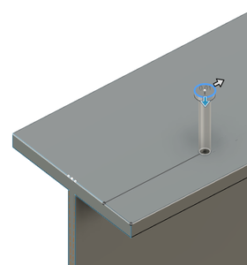
Step 18: Beams and Shear Connectors: (3) Adding More Shear Connectors
Purpose: According to Trimble, the spacing of connectors along the beam should be at least 6 times the stud diameter and the spacing across the beam should be at least 4 times the stud diameter.
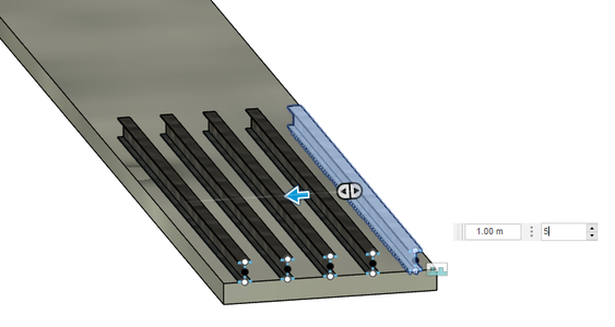
How-to: Select the shear connector and open the rectangular pattern tool. Along the length of the beam, the quantity will be 59 and the spacing between connectors will be 0.2 m. Transversely across the beam, the quantity will be 2 and the spacing will be 0.15 m.
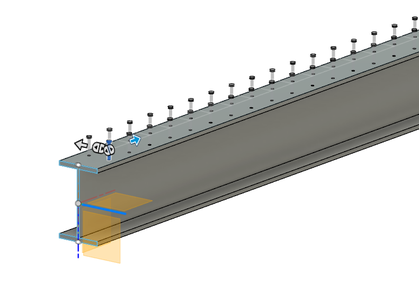
Step 19: Beams and Shear Connectors: (4) Joining the I-beam to the Concrete
Purpose: By joining the I-beam to the concrete using the flange with the shear connectors at the contact point, it allows shear forces to transfer between the concrete, rebar, and steel beams.
How-to: Drag the I-beam into the bridge drawing as a component. Use the joint tool and select the flange of the I-beam with the shear connectors as the first snap. The second snap should be one of the large faces of the concrete bridge. Drag the I-beam so it is 0.5 m away from the edge of the walkway.
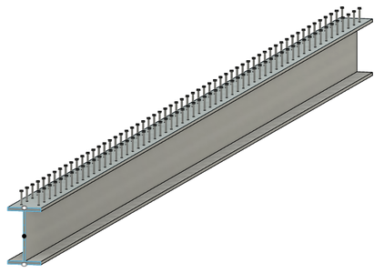
Step 20: Beams and Shear Connectors: (5) Adding More I-beams

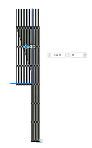
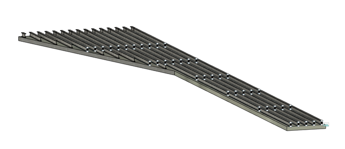
How-to: The I-beams need to be laid across the length of the bridge sector. The best way to do this is by using the rectangular pattern tool with the object type on component. Select the I-beam; for the axis along the length of the bridge, lay 7 I-beams 12 m apart. For the axis across the bridge, lay 5 I-beams 0.5 m apart.
For the section where the path widens, do another rectangular pattern. This time, for the axis along the bridge, lay 4 I-beams 12 m apart, and for the axis across the bridge, lay 10 I-beams 0.5 m apart.
Step 21: Beams and Shear Connectors: (6) Removing Extra I-beams
Purpose: Similar to what happened with the rebar, extra beams were layed to compensate for the larger portion for the bridge. Now, the extra I-beams must be removed.
How-to: Use one of the large faces of the bridge as a sketch plane. Use the line tool to outline a large shape enclosing any extra I-beams that did not make it into the concrete. Then, extrude the enclosure by -1 m, ensuring that the extrusion is on the cut operation.
Construction:
- Preparation of Steel I-Beams: The steel I-beams, which are pre-fabricated off-site to the required specifications, are transported to the construction site. These beams are designed to carry additional loads and support the bridge's modified configuration.
- Placement of I-Beams: The I-beams are carefully positioned and secured on the existing bridge structure using cranes or other lifting equipment.
- Welding and Connection: Once the I-beams are in place, they are welded or bolted to the existing bridge structure to create a strong connection. This step ensures that the I-beams and the bridge act as a unified structure to carry the loads.
- Addition of Shear Connectors: Shear connectors are attached to the top flange of the steel I-beams. These connectors play a crucial role in transferring the shear forces between the concrete deck and the steel beams, enhancing the composite action of the structure.
- Concrete Placement: After the I-beams and shear connectors are in position, a new concrete deck is poured and formed on top of the steel beams. This concrete deck, together with the I-beams and shear connectors, forms a composite bridge structure capable of carrying heavier loads.
Step 22: Braces: (1) Creating the Beam Braces

Purpose: Bracing between I-beams helps prevent lateral buckling by providing additional stiffness and support, ensuring that the beams maintain their straight alignment and do not buckle under compression. Additionally, the bracing helps to transfer forces and redistribute them among the beams, thereby increasing their collective load-carrying capacity; it allows for the load to be shared between the beams more evenly, preventing individual beams from being overloaded.
How-to: Select the side of the beam that is shaped as an "I" as the sketch place. Create a rectangle across the bottom and top flange of the I-beam, each 0.03 m long. Use the midpoint of the bottom rectangle to sketch two more rectangles, each snapped diagonally to the top flanges of the 2 I-beams with a width of 0.03 m.
Extrude the shape by 0.03 m and ensure that the appearance is steel-cast.
Step 23: Braces: (2) Adding More Beam Braces
Purpose: The braces are going to be installed every 6 m along the length of the beams; this results in a more rigid system, minimizing excessive deflection and maintaining the structural integrity.
How-to: Use the rectangular pattern tool to first lay 4 braces 1 m apart along the axis across the bridge. Then, lay 13 braces 6 m apart along the axis that carries through the length of the bridge. The rectangular pattern tool will need to be used 5 more times to fill the wider side of the bridge with braces.
Construction:
- Positioning the Beam Braces: The beam braces are positioned in the designated locations on the bridge. This may involve using cranes or other lifting equipment to hoist the braces into place.
- Connection to the Bridge: The beam braces are connected to the bridge's main structural elements, such as the girders or trusses. The connections are designed to provide secure and stable attachment points.
- Alignment and Adjustment: Once the beam braces are connected, they are aligned and adjusted to the required angles and lengths to ensure proper bracing and support.
- Welding or Bolting: The beam braces are either welded or bolted to the bridge's main structural elements. Welding provides a permanent and robust connection, while bolting allows for some adjustability and ease of replacement if needed.
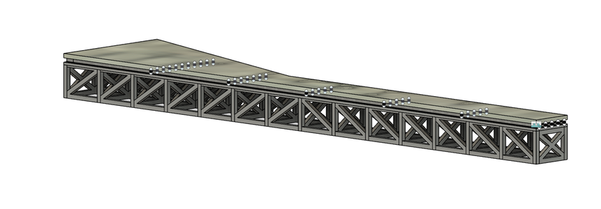
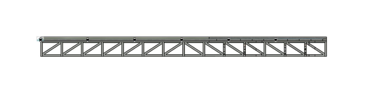
Step 24: Truss: (1) Sketching the First Truss Section of the Base
Purpose: This bridge is going to be a truss deck bridge. Placing the truss below the bridge deck allows for a continuous load path from the deck to the truss, effectively distributing and transferring the load throughout the structure. In addition, with the truss elements located below the deck, the visible portion of the bridge can have a clean, uncluttered appearance. This allows for greater design flexibility, enabling me to later create a visually appealing structure that complements the surrounding landscape. And, most importantly, placing the truss below the deck makes routine inspections, maintenance, and repairs more accessible and convenient. The truss members can be easily accessed from below, reducing the need for extensive scaffolding or complicated procedures to reach critical components.
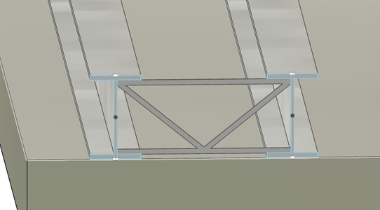
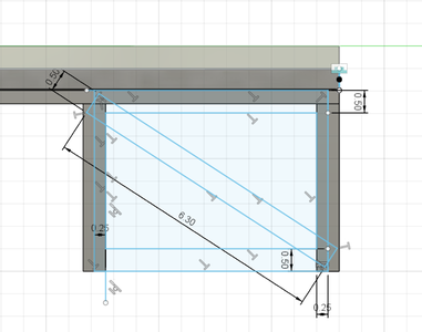
How-to: To create one of the bases of the truss, select the flange of the I-beam as a sketch plane. Start with a 0.5 m outline of the bridge. Starting at the edge of the walkway, use the rectangle tool to create a 5 m x 5 m square. Use the line tool to create a 0.5 m thick outline within the square. Then, anywhere on the sketch plane, create a 6 m x 0.5 m rectangle. Create a copy of this rectangle and use the rotate/move tools to create an "x" shape within the square.
Use the trim tool to remove any excess lines to clean up the shape.
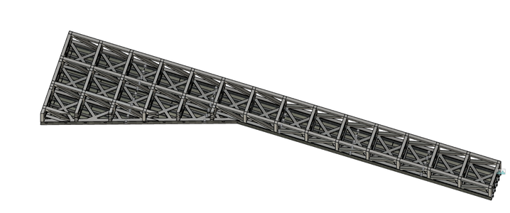
Step 25: Truss: (2) Completing the Base Truss
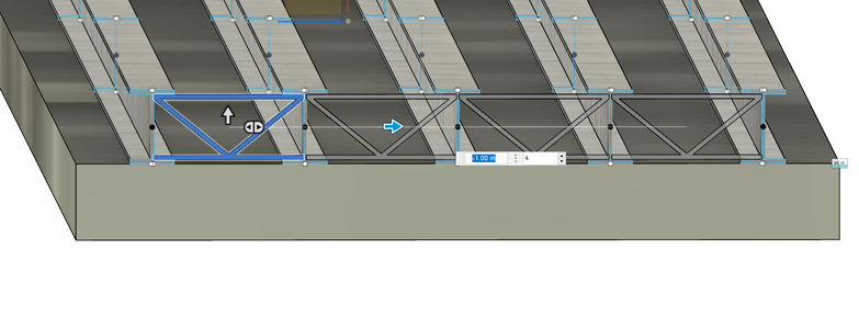
How-to: Open the rectangular pattern tool and select the truss shape. Snap the extent of the pattern to the opposite end of the bridge and make the quantity 14. Repeat this in order to fill the remaining section of the bridge with the truss.
Use the trim tool to remove any lines that go past the extent of the bridge. Then, extrude the shape by 0.3 m.
Step 26: Truss: (3) Creating the First Inner Truss
Purpose: Truss bridges work on the principle of triangulation, where the triangular shapes of the truss members help to distribute the applied loads evenly. Inner truss members provide additional triangulation, ensuring that the loads are efficiently transferred from the top chord to the bottom chord and ultimately to the bridge's piers or abutments. The inclusion of inner truss members adds redundancy to the bridge's design; if one truss member were to fail, the other members can still support the load and prevent a catastrophic failure. This redundancy enhances the safety of the bridge and helps prevent sudden collapses.
How-to: Select the short front side of the walkway as a sketch plane. Sketch a 5 m x 3.7 m rectangle and create a 0.5 m thick outline within the square.
Then, anywhere on the sketch plane, create a 5.3 m x 0.5 m rectangle. Create a copy of this rectangle and use the rotate/move tools to create an "x" shape within the rectangle.
Use the trim tool to remove any excess lines to clean up the shape. Then extrude the shape as a new body by 0.5 m.
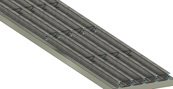
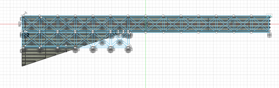
Step 27: Truss: (4) Duplicating the Inner Truss
How-to: Using the rectangular pattern tool, snap the extent of the pattern to the opposite end of the bridge and make the quantity 15.
Starting from the wide corner of the bridge, use the rectangular pattern tool to lay a 6-truss section x 3 truss section area to fill the wider part of the bridge. Use the slider tool to snap the sides to the previously laid trusses.
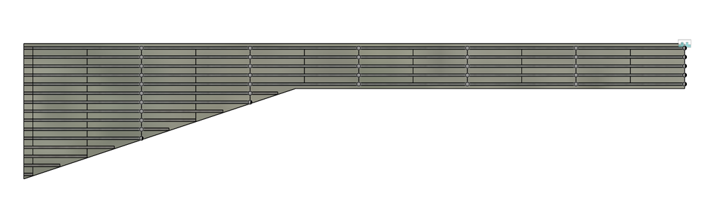
Step 28: Truss: (5) Removing Extra Trusses
How-to: Select the flat side of the concrete as a sketch plane and use the line tool to create a shape enclosing any extra material that is outside the bounds of the concrete.
Extrude by -10 m and ensure the operation is on cut.
Step 29: Truss: (6) the Intial Howe Truss
Purpose: This bridge is going to use the howe truss; it consists of diagonal members that slope downward and away from the center of the span. These diagonal members form a series of V shapes within the truss structure. The combination of diagonal and vertical members provides rigidity and resistance against bending and twisting forces, making it suitable for medium to long span bridges. The sloping orientation of the diagonals efficiently transfers the vertical and horizontal loads to the supports, distributing the forces along the truss members.
Two of the strongest and most used trusses are the Howe and Pratt design. Through a study from West Kentucky Community and Technical College, it was found that the howe bridge was the most apt in minimizing the largest compression force.
How-to: Select the side of the bridge as a sketch plane. Between two trusses, create a center rectangle by snapping the length to the bottom of the trusses, then snap the width to the middle of the trusses.
Create a second center rectangle, this time snapping the width to the inner side of the truss and leaving a length of 3 m.
Then, anywhere on the sketch plane, create a 6.3 m x 0.5 m rectangle. Create a copy of this rectangle and use the rotate/move tools to create a diagonal going from the top left to the bottom right corner.
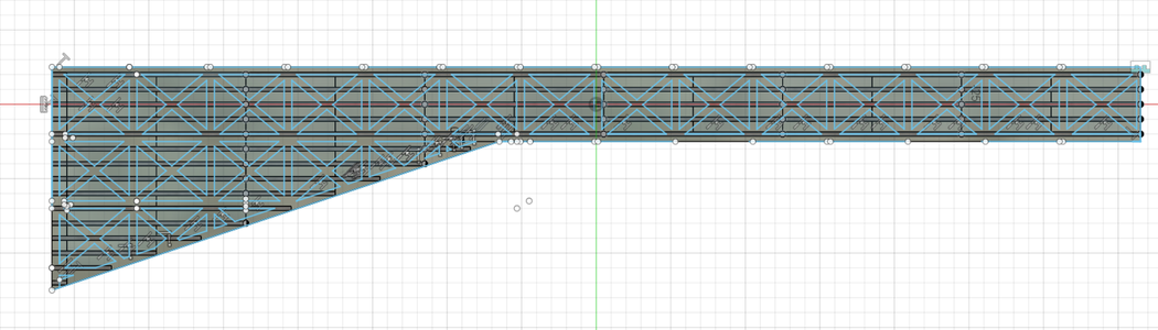
Step 30: Truss: (7) Duplicating the Howe Truss
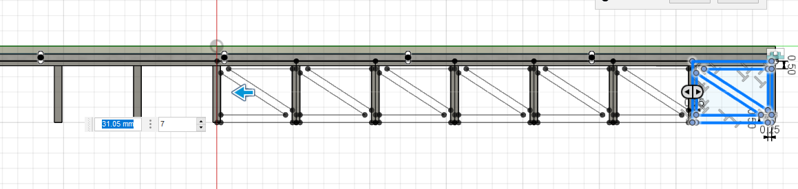

How-to: Use the rectangular pattern tool to snap the extent to the center truss and make the quantity 7. Then, mirror the truss along the center of the bridge and extrude by -0.5 m, ensuring the operation is on new body.
Use the rectangular pattern tool to lay 3 more Howe trusses along the rest of the bridge.
Step 31: Truss: (8) Removing Extra Howe Trusses
How-to: Select the flat face of the concrete as a sketch plane. Use the line tool to enclose any trussing that made it past the extent of the bridge in the previous step. Extrude by -10 m and ensure that the operation is on cut.
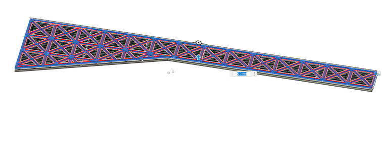
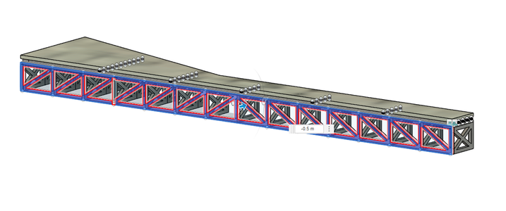
Step 32: Truss: (9) Adding the Final Base to the Truss


How-to: Open the rectangular pattern tool and select the bottom base truss; the pattern will carry on the axis along the height of the bridge. Snap the extent to the very bottom of the truss and make the quantity 2.
Construction:
- Prefabrication of Truss Members: The truss members are prefabricated off-site in a factory or fabrication shop. This involves cutting the steel to the required lengths and shaping them according to the design specifications.
- Transportation to the Bridge Site: After fabrication, the truss members are transported to the bridge construction site. Depending on their size and weight, they may be transported using trucks, trailers, or barges.
- Assembly of the Truss: The assembly of the truss takes place at the bridge site. Typically, the truss is assembled on temporary supports adjacent to the bridge location. Cranes or specialized lifting equipment are used to position and hold the truss members in place during assembly.
- Bolted or Welded Connections: The truss members are connected to each other at their joints using bolts or welds.
- Truss Erection: Once the truss is fully assembled, it is lifted into its final position on the bridge piers or abutments. Cranes or specialized lifting systems are employed to hoist the truss into place and secure it to the bridge supports.
Step 33: The Bike Paths and Sidewalks
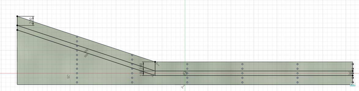

Purpose: The sidewalk is going to be made from concrete tile; it is generally cost-effective compared to other sidewalk materials like natural stone or brick. It offers a balance between durability, aesthetics, and affordability. Additionally, concrete tile sidewalks can be designed with features that promote water drainage and permeability, minimizing stormwater runoff and contributing to sustainable urban design.
One important decision in this project was to have separate paths for bikes and pedestrians. According to a study published in the Journal of Transport & Health, dedicated bicycle infrastructure, including separate paths, significantly reduces the risk of crashes and injuries for both cyclists and pedestrians. Separate paths help eliminate conflicts between faster-moving bicycles and slower pedestrians, reducing the potential for collisions. When cyclists and pedestrians have separate paths, it creates a more pleasant experience for both user groups; pedestrians can walk without concerns about bicycles passing closely, and cyclists can ride at a comfortable pace without constantly navigating around pedestrians. This improves overall user satisfaction and encourages active transportation.
How-to: Select the concrete side as a sketch plane. Starting 2 m down from the walkway, create a 1 m path that follows the bend in the shape of the bridge. Extrude by 0.1 m as a new body and make the material concrete tile.
Create the same shape below the sidewalk, but this time extruding by 0.05 m and with the material set to asphalt.
Then, enclose the remaining section of concrete below the asphalt path. This will be another sidewalk, so extrude by 0.1 m and make the material concrete tile.
Construction:
- Base Preparation: A stable and durable base is crucial for the longevity of the path. The construction team prepares the sub-base with materials such as crushed stone or gravel to provide a solid foundation.
- Formwork: In some cases, formwork or molds are used to shape the edges of the path. This is more common when constructing concrete sidewalks.
- Concrete Pouring: For concrete sidewalks, the concrete mixture is poured into the prepared area and spread evenly to fill the formwork or shape the path.
- Asphalt or Paving: If the path is made of asphalt or other paving materials, a paving machine is used to lay the surface smoothly and evenly.
- Compaction: The base material and/or surface material are compacted using heavy machinery to ensure stability and eliminate air pockets.
- Curing: If concrete is used, a curing process is employed to allow the concrete to gain strength and durability. Curing may involve covering the concrete with wet burlap or using curing compounds.
Step 34: The Gardens

Purpose: The bridge is to be surrounded by gardens on either side. Of course, adding gardens would be the most direct way to connect humans to nature, I also wanted to consider gardens from an aboriginal perspective. Gardens hold spiritual significance in many native cultures. They may be considered sacred spaces where rituals, ceremonies, and gatherings take place. Plants and gardens are often regarded as intermediaries between humans and the spiritual realm, enabling a connection with ancestral spirits and promoting a harmonious relationship with the natural world. Having gardens will help exemplify the principles of environmental sustainability and stewardship.
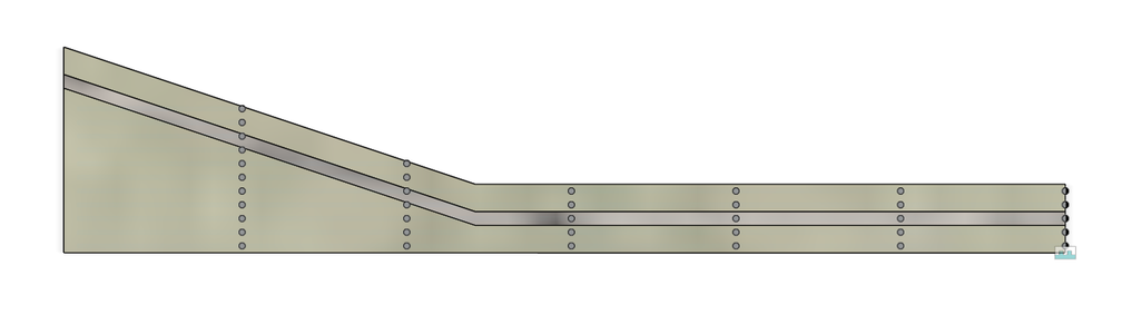
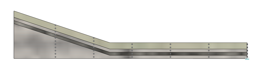
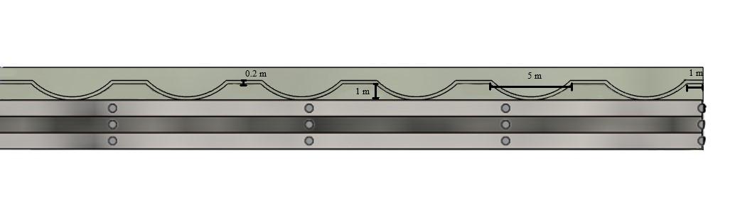
How-to: Start 1 m down from the edge of the walkway. Sketch a 1 m line followed by an arch with a height of 1 m and a width of 5 m. Following the arch, create another 2 m line. Repeat the arch and the 2 m line until the end of the walkway is reached.
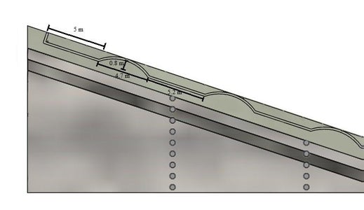
For the wider portion of the bridge, start with an arch with a width of 4.7 m and a height 0f 0.8 m. Following with a 5.2 m line. Repeat this sequence for 3 arches. After the third arch, create a 5 m line with a line pedicular to this that snaps to the edge of the bridge.
Create a 0.2 m thick outline above the enclosure. Extrude the garden enclosure by 0.5 m as a new body and make the appearance white marble.
*The gardens will be completed after the bridge has been completely mirrored.
Construction:
- Fabrication of Granite Barriers: Once the granite is selected, it is transported to a fabrication facility, where it is cut, shaped, and polished to the required dimensions and finish. The fabrication process ensures that the granite barriers are precisely made according to the garden's design.
- Transportation and Installation: The fabricated granite barriers are transported to the garden site. Cranes or other heavy machinery are used to lift and carefully place the granite barriers in their designated locations. The installation process requires precision to ensure the barriers are level and properly aligned.
- Foundation and Anchoring: Depending on the size and weight of the granite barriers, a concrete foundation or footing may be constructed to provide additional stability. In some cases, metal anchors or connectors are used to secure the barriers to the foundation or to each other.
- Finishing and Sealing: Once the barriers are in place, any joints or seams are filled, and the granite surfaces are sealed to protect them from stains and weathering. The sealing process also enhances the granite's natural beauty.
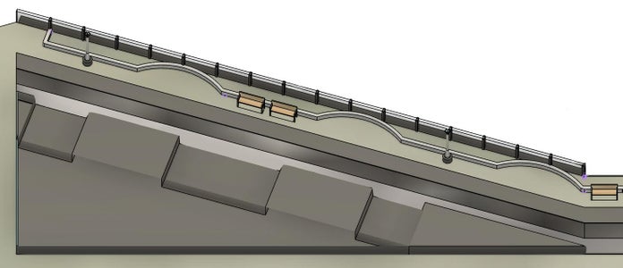
Step 35: Benches: (1) Creating the Benches

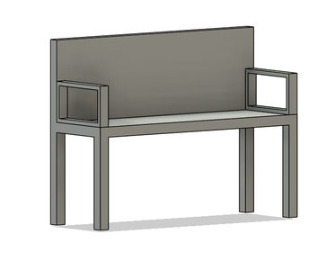
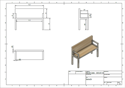
Purpose: Since the bridge covers a slightly larger span, it will need benches. First and foremost, adding benches to a bridge allows people to take a break, sit down, and enjoy the surrounding views. It provides a resting spot for pedestrians or cyclists who may need to catch their breath or simply take a moment to relax. However, by incorporating benches, people also have the opportunity to appreciate and enjoy the natural surroundings or architectural features at a leisurely pace. It encourages a deeper connection with the environment and promotes a sense of mindfulness and tranquility.
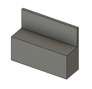
How-to: Create a new drawing and start by extruding a 0.9 m x 0.4 m x 1.2 m rectangular prism. Select the 0.4 m x 1.2 m face as a sketch plane, and extrude a 0.35 m x 1.2 m rectangle by 0.4 m.
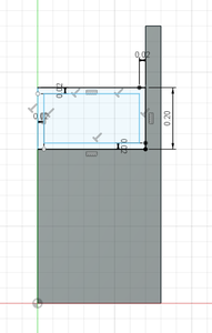
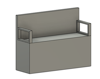
To create the arm rests, select the side of the bench as a sketch plane and sketch a 0.2 m x 0.3 m rectangle with a 0.02 thick outline inside. Extrude the shape by 0.05 m and repeat on the other side of the bench.
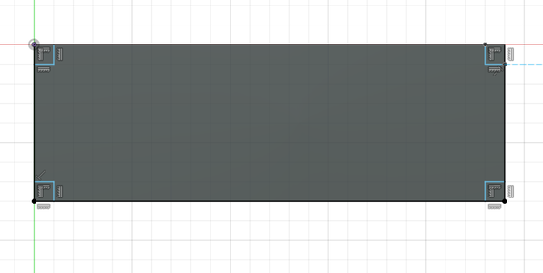
In order to create the legs, select the underside of the bench as a sketch plane. Sketch 0.05 m x 0.05 m squares in each corner. Extrude the area around the square by 0.45 m.
Make the arm rests and legs of the bench made of iron-cast and the seating area of cedar.
Step 36: Benches: (2) Laying the Benches
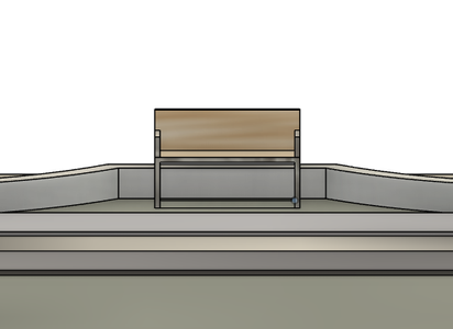
How-to: Add the bench as a component into the bridge drawing. For the walkway, drag the first bench to the area after the second arch. Add two more benches, one after every other arch.
For the larger section of the bridge, 2 benches are to be laid side by side after the second arch.
Construction:
- Procurement: The benches are purchased from suppliers or manufacturers based on the chosen design and specifications.
- Surface Mounting: Since the benches made of wood and metal, surface mounting is a common method. In this approach, the bench is secured to the concrete surface using anchor bolts or screws. The bench legs or base have pre-drilled holes where the fasteners are inserted, and then they are tightened to firmly attach the bench to the ground.
Step 37: Street Lights: (1) Creating Street Lights

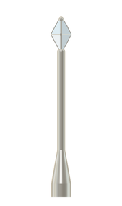
Purpose: Since bridges are elevated structures, adequate lighting is essential to ensure visibility and safety for cyclists and pedestrians using the bridge. Moreover, adequate lighting on bridges can help deter criminal activities and improve security. Well-lit areas create a sense of safety and can discourage potential offenders. Lighting also enhances surveillance capabilities, making it easier for security personnel or surveillance systems to monitor the bridge and its surroundings.
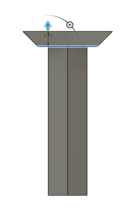
How-to: Start by extruding a 0.2 m long cylinder with a diameter of 0.3 m. Make the appearance aluminum - satin. Then, extrude one of the circular faces of the cylinder by 0.5 m with a taper angle of -10.
Extrude the smaller circular face by 1.5 m.
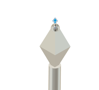
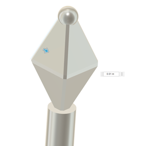
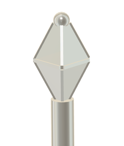
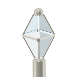
Select the smaller circular face as a sketch plane. Create a 0.57 m x 0.57 m center square and extrude by 0.22 m with a taper angle of 20. Then, extrude the larger square face by 0.22 m with a taper angle of -20 deg. At the top, extrude a sphere with a dimeter of 0.09 m.
Then, chamfer all the edges for the shape created at the top of the streetlight pole by 0.01 m. Extrude the chamfered edges by 0.01 m.
For the top portion of the streetlight, change the appearance to glass - light colour (blue).
Step 38: Street Lights: (2) Laying the Street Lights

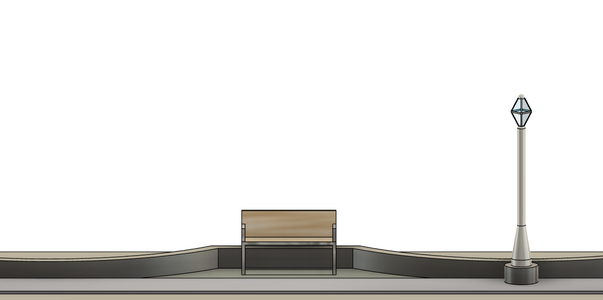
How-to: Start with the second arch on the walkway and select the sidewalk as a sketch plane. Snap to the center of the arch and extrude a 0.3 m cylinder with a diameter of 0.5 m.
Snap to the center of the circular face of the cylinder and extrude a cylinder with a dimeter of 0.3 m and a height of -0.1 m, ensuring that the operation is on cut. This will be the fixture for the streetlight.
Drag the streetlight into the drawing as a component. Use the joint tool to attach the bottom face of the streetlight to the inner circular face of the fixture.
Repeat this twice more for the remainder of the walkway, attaching a streetlight after every other arch.
For the larger section of the bridge, lay 2 streetlights, each centred in front of straight sections of the garden enclosure.
Construction:
- Utility Connections: Streetlights require electrical power, so connections to the local power grid need to be established. This may involve coordination with the local utility company.
- Foundation and Infrastructure Preparation: Suitable foundations for the streetlight poles are installed. The type of foundation depends on the streetlight design and local soil conditions. Wiring trenches may also be dug to accommodate the electrical cables that will connect the streetlights.
- Streetlight Installation: The streetlight poles are erected and secured on the prepared foundations. Luminaires (light fixtures) are attached to the top of the poles.
- Electrical cables are run from the streetlights to the power source, which is often located in nearby electrical cabinets or underground utility boxes.
Step 39: Artisan Booths
Purpose: Due to consumer-apathy and lack of opportunities, the number of indigenous craftspeople has been on a steady decline. Artisans play a vital role in preserving and promoting Indigenous cultural traditions; by supporting them, it contributes to the preservation of traditional artistic practices, techniques, and designs that have been passed down through generations. This helps ensure the continuity and vitality of Indigenous cultures.
This is why I wanted to use my bridge to create economic opportunities for the first nation people of Calgary. Having selling booths dedicated towards native artisans ensures the preservation and promotion of authentic Native American art, ensuring that it is not diluted or misrepresented by non-Indigenous imitations. It helps create platforms for Indigenous self-representation and challenges stereotypes and misconceptions that exist about Native American communities.
Most importantly, supporting Native American artisans is an act of social justice and equity. It acknowledges the historical injustices and ongoing struggles faced by Indigenous communities. Therefore, it helps counteract the systemic marginalization and cultural appropriation that has impacted Native American art and artisans. Supporting artisans is a step towards creating a more equitable and inclusive society.
How-to: Create a new drawing and start with a 2 m line. One either end of the line, snap an arc that goes 0.8 m down and 1.3 m to the side. Create a 0.1 m outline below and then extrude the shape by 1.4 m.
Select the bottom of the booth as a sketch plane and enclose a 0.3 m thick area from the end of the arcs. Remove a 0.3 m x 0.5 m rectangle as an entrance. Then, extrude the section by 0.8 m. Change the appearance to cedar.
Drag the booths in the bridge drawing as a component. Use the joint tool to attach the first booth after the first arch in the walkway's garden. Join one more booth before the final arch along the walkway.
Construction:
- Foundation and Support: Ensure the booths have a stable foundation and proper support to withstand wind, rain, and foot traffic. Depending on the design and location, this may involve concrete footings or a platform that provides stability.
- Construction and Assembly: Assemble the wooden booths according to the approved design. Use proper construction techniques, such as secure fastening with screws or bolts, to ensure the structural stability of the booths.
- Finishing: Apply finishes and coatings to protect the wood from weathering.
- Signage and Branding: Add signage and branding elements to identify the booths and showcase the artisans' work.
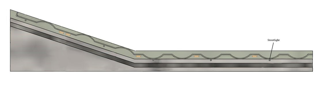
Step 40: The Information Board
Purpose: Recognizing past acts committed against Native people can contribute to justice and accountability as it helps ensure that the historical injustices faced by Indigenous communities are not forgotten or repeated. This can be done through an information board.
By presenting accurate information, it challenges historical narratives that may have minimized or excluded the experiences of Native people. It provides an opportunity for individuals to learn about the historical context and the impact of colonization, forced assimilation policies, land dispossession, and other injustices. It raises awareness and promotes a more accurate and empathetic understanding of Indigenous history and experiences.
Educating people on the atrocities committed against indigenous validates their experiences, affirms their collective resilience, and contributes to their healing and cultural revitalization. Having information boards in my design helps bridge gaps in knowledge, promotes empathy, and encourages non-Indigenous individuals to become allies in addressing historical and ongoing injustices.
Some topics that the information boards could touch on are:
• Indian Residential Schools
• Forced Relocation and Displacement
• Land Dispossession
• Cultural Suppression and Assimilation
• Conflicts and Massacres
• Forced Sterilization
How-to: Create a new drawing a start with a 2 m line. On either end, extend a line 0.7 m down and 1 m to the side. Create a 0.07 m thick border below these lines and add a circle with a diameter of 0.14 m at each point. Extrude the shape by 1 m. Extrude the circles by another 0.5 m.
The board material should be aluminum and the poles should be cedar.
Drag the information board as a component into the bridge drawing and join it the bridge after the third arc along the walkway.
Construction:
- Construction: Construct the frame or support structure for the information board using the selected materials. Ensure that it is sturdy, durable, and able to withstand outdoor weather conditions.
- Graphics and Content: Prepare the graphics, text, and images that will be displayed on the information board. Use weather-resistant and fade-resistant materials for printed content to ensure longevity.
- Weather Protection: If the information board is not fully enclosed, a clear protective cover should be added to shield the content from rain, wind, and other environmental elements.
- Mounting and Installation: Securely mount the information board. Depending on the design, this may involve using bolts, screws, brackets, or other mounting hardware.
Step 41: Railing
Purpose: Only the wider section of the bridge is going to need a railing since the walkway is going to have a tunnel. I decided to have railings made of glass panels with supporting aluminum posts every 1.75 m. Unlike solid barriers or railings made of other materials, a glass railing offers minimal obstruction to the view. It allows pedestrians and drivers to enjoy unobstructed panoramas and maintain a sense of openness while crossing the bridge. This can be particularly advantageous in the area around Baker Park and Bowness Park where there are beautiful landscapes, architectural landmarks, and waterfront views: the objective is to maximize the visual experience. The sleek and modern appearance of glass can also enhance the aesthetic value of the bridge and integrate it harmoniously with the surroundings.
How-to: Select the concrete as a sketch plane. Along the edge of the wider section of the bridge, sketch a 32.5 m x 0.15 m rectangle and extrude by 1 m as a new body.
Select the top of the railing as a sketch plane and create seventeen 0.25 m x 0.1 m rectangles along the top of the railing spaced at 1.85 m intervals. Extrude the smaller rectangles by 1 m as a new body.
Change the appearance of the panels to glass and the supporting posts to aluminum.
Construction:
- Frame Installation: In framed glass railings, metal frames are used to support and encase the glass panels. The frames are installed on the bridge's edge, and the glass panels are inserted into the frames.
- Glass Panel Fixing: The glass panels are secured to the frames using clips, brackets, or gaskets. These fixtures hold the glass panels firmly in place while allowing some flexibility for thermal expansion and contraction.
- Finishing and Weatherproofing: The frames and glass joints are sealed with appropriate weatherproofing materials to protect against moisture and harsh weather conditions.
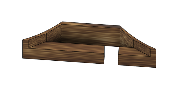
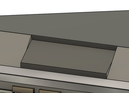
Step 42: The Stage Base
Purpose: I wanted to include a stage in my design because I believe that Calgary needs a gathering point, it needs a place to bring people together and where community bonds can be strengthened. A stage serves as a space where individuals can connect, interact, and celebrate their shared heritage. However, I wanted this stage to be dedicated to something more specific: potlatches.
The potlatch is a ceremonial event practiced by various Indigenous cultures of the Pacific Northwest Coast of North America, particularly among the First Nations peoples. It holds great importance in these societies and carries cultural, social, and economic significance. They provide opportunities for families and clans to come together, share experiences, and reinforce their collective identity.
Early European settlers, missionaries, and Canadian authorities initially misunderstood and criticized the potlatch. They saw it as wasteful, extravagant, and a barrier to assimilation. As a result, the potlatch was banned by the Canadian government in the late 19th century under the Indian Act, from 1884 to 1951. The ban was part of a larger effort to suppress Indigenous cultural practices and assimilate Indigenous peoples into Euro-Canadian society.
Despite the ban, many Indigenous communities continued to practice the potlatch in secret or modified forms. Today, the potlatch remains a vibrant and integral part of Indigenous cultures in the Pacific Northwest. I want to give native people a place that is dedicated towards only of the most important concepts in their culture. Having a stage for potlatches on my bridge helps foster indigenous people as a symbol of resilience, cultural resurgence, and pride. Potlatches are important occasions for strengthening Indigenous identity, community connection, and the preservation of traditional knowledge.
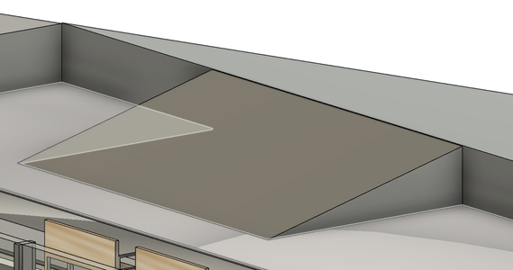
How-to: Select the larger portion of the sidewalk as a sketch. From the corner, sketch a right-angle triangle with a base of 30 m and a height of 10 m. Extrude the shape by 0.8 m. Select the top of the bridge as a sketch plane and create a 3 m thick outline along the hypotenuse. Cut a 3 m x 3m square on both end of the smaller right-angle triangle. Along the center of the hypotenuse of the smaller triangle, cut a 3 m x 5.8 m rectangle.
Construction:
- Build the Frame: Construct the frame of the stage using the selected wood and appropriate fasteners. The frame should be sturdy and securely anchored to the bridge surface.
- Decking: Install the wooden decking on top of the frame. Secure the decking boards with screws to ensure stability and durability.
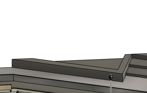
Step 43: Ramps and Stairs

Purpose: Since the stage is a raised platform, stairs and ramps are needed to access it. According to Intermat, stair rise should be from 5-8 in. These stairs will have a rise of 20 cm (≈7.87 in). I decided to include ramps up to the stage as well to make the public space more accessible and inclusive for people with mobility disabilities. By removing physical barriers, public ramps promote social interaction and integration.
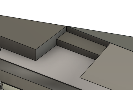
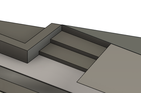
How-to: Firstly, there are going to be two ramps on each bridge section; select one of the raised platforms along the edge of the stage as a sketch plane. Trigonometric ratios were used to determine the slant angle of the ramp. If the rise is 0.8 m and the run is 3 m, the slant angle must be angling 15 deg. Next to both sets of stairs, select the top surfaces of both platforms, and draft the sides by 15 degrees.
Next to each ramp will be a set of stairs. Select the sidewalk as a sketch plane. Then, in the two cut sections along the corners of the stage, create a 0.98 m x 3 m rectangle and extrude by 0.4 m. Then, create another rectangle with the same dimensions next to it, but extrude by only 0.2 m.
Construction:
- Fabrication of Granite Components: The selected granite is transported to a fabrication facility, where it is cut, shaped, and finished to the required dimensions and design. Steps, landings, and ramps are fabricated to match the bridge's specifications.
- Installation of the Foundation: A stable and properly constructed foundation is essential for the longevity of the granite stairs and ramps. Concrete footings are typically installed to support the weight of the granite components.
- Placement of Granite Components: The fabricated granite stairs, landings, and ramps are transported to the bridge site and carefully placed on the prepared foundation. Cranes or other lifting equipment may be used to position the heavy granite pieces accurately.
- Bonding and Jointing: Adhesive materials are used to bond the granite components together and create a seamless and stable surface. Special attention is given to the jointing to ensure a tight fit and prevent water infiltration.
- Finishing and Sealing: The surface of the granite is polished and finished to achieve the desired texture and appearance. Additionally, the granite is sealed to protect it from staining and weathering, and to enhance its natural beauty.
Step 44: Center Tree Garden
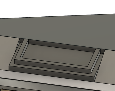
Purpose: I also wanted to include tree gardens in the bridge. Trees are often considered sacred and are believed to have spiritual qualities; many native communities use the leaves, bark, and roots for healing or medicinal purposes. Moreover, native cultures have traditionally practiced sustainable resource management, which involves using trees and other natural resources in a manner that ensures their regeneration and long-term availability. Finally, trees often play a central role in myths, legends, and creation stories of native cultures; they are part of the cultural identity and traditions, forming the foundation of their belief systems and way of life.
How-to: In the cut section along the center of the stage, use the rectangle tool to enclose the area and then extrude it by 0.4 m.
Select the top surface of the shape as a sketch. Along the side against the stage, create a 2.65 m x 5.18 m rectangle with an inner outline that is 0.3 m thick. Extrude the section by 0.35 m.
Construction:
See Construction in Step 30.
Step 45: Fountain Reservoir
Purpose: Water is fundamental to all life on Earth, and native cultures recognize its significance as the source of life. They understand that water sustains not only human communities but also plants, animals, and ecosystems; in regions where waterways are prevalent, boats and canoes have historically been essential means of transportation for native communities.
Although the bridge itself would be over a body of water, I wanted to include something on the deck that would connect to the significance and spirituality associated with water: a water fountain.
The reservoir is designed to collect and hold the water that will be used for the fountain. I decided that inside the reservoir, there there will be submersible pump located at the bottom which draws water from the reservoir and pushes it through the fountain's plumbing system. However, I found that the reservoir itself will need a water supply and a good candidate would be the Bow River. The bridge runs right over this body of water which allows water to be carried up through a plumbing system consisting of pipes and nozzles that distributes the water from the pump to the jets. This feature can be arranged in different patterns and configurations to achieve the desired visual effect; I plan to build a pyramid-like skeleton that carries the pipes through the posts to create a criss-cross-like pattern with the water streams. I would also need to consider how the water would be recycled, so once the water has been pumped through the plumbing system and used to create the fountain effect, it returns to the reservoir. The recirculation process ensures that the same water is continuously reused, making the fountain more water-efficient.
How-to:
At this point, only the reservoir will be built, the actual fountain will be designed when the bridge sector is mirrored. Along the corner of the stage, select the platform shaped as a right-angle triangle as a sketch plane. Create a 0.5 m thick outline within the shape and extrude the inside by -0.35 m with the cut operation.
Construction:
- Foundation and Structure: Depending on the reservoir's size and weight, a proper foundation may be required to support the reservoir's weight. This foundation may involve reinforcing the bridge structure or adding additional support elements.
- Waterproofing: Ensure that the reservoir is properly waterproofed to prevent leaks and water seepage. Waterproofing membranes or coatings may be applied to the reservoir walls and floor to create a watertight seal.
Step 46: Stage Appearances
How-to: Apply a white granite appearance to the stairs and the garden and a red granite appearance to the fountain reservoir and ramps. The stage deck will be made out polished cedar wood.
Step 47: Drip Irrigation Sysmtem

Purpose: For the gardens along the bridge, I wanted to use a drip irrigation system; drip irrigation is a method of delivering water directly to the roots of plants in a controlled and efficient manner. It involves the use of a network of tubes or pipes that have small openings, called emitters or drippers, spaced along their length. These emitters release water slowly and evenly, allowing it to drip directly onto the soil near the plants' root zones. Drip irrigation is highly efficient in delivering water directly to the root zone of plants, minimizing water loss due to evaporation or runoff. Unlike traditional watering methods like sprinklers, which can waste water through overspray, drip irrigation ensures that water reaches the plants' roots precisely where it's needed.
The irrigation system will run through the deck of the bridge where a pump by the foundation blocks will distribute water directly from the river to the irrigation pipes.
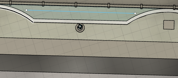
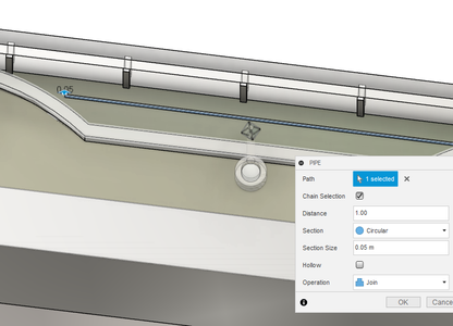
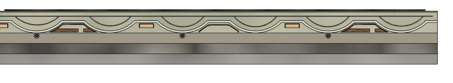
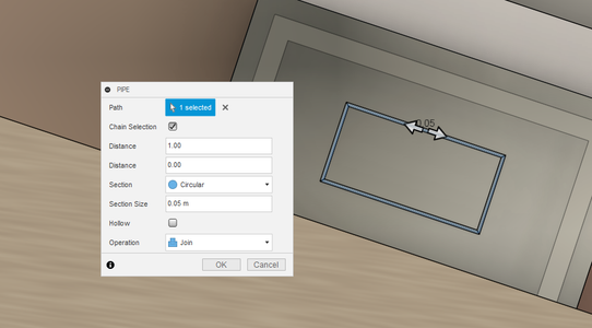
How-to: Select the inside of the gardens as a sketch plane and draw a straight line going across the length of the garden. The line will be a pathway for when we use the pipe tool; create a pipe along the line and make the section size 0.05 m. Repeat this for all of the gardens along the larger side of the bridge.
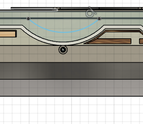
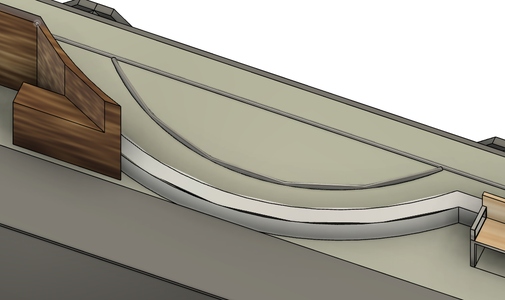
Along the walkway, start with one long pipe through the gardens with a section size of 0.05 m. Where there are arcs, lay an arched pipe with a height of 0.8 m and a width of 4 m.
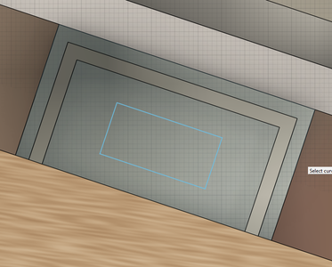
Then, for the tree garden by the stage, sketch a 1.2 m x 2.4 m rectangle. This creates a rectangular pathway for the pipe.
Finally, change the appearance of all of the pipes to PVC.
Construction:
- Tubing Installation: Lay the main distribution tubing along the desired irrigation lines on the bridge. This tubing will supply water to the various plant areas.
- Emitters Placement: Install drip emitters or micro-sprinklers at appropriate intervals along the tubing, based on the watering needs of the plants. Ensure that each plant receives the required amount of water.
- Connection to Water Source: Connect the main distribution tubing to the water source. This may involve using fittings and connectors to make secure and watertight connections.
- Filter and Pressure Regulation: Install a filter and pressure regulator in the irrigation system to prevent clogging of emitters and to ensure a consistent water flow to all plants.
- Controller Installation: If an automated system is desired, install an irrigation controller or timer. This allows you to set specific watering schedules and duration, optimizing water usage and plant health.
- Testing and Adjustments: Before fully implementing the irrigation system, thoroughly test it to identify any leaks, clogs, or inefficiencies. Make any necessary adjustments to ensure proper watering and coverage.
Step 48: Information Pedestal
Purpose: The bridge is going to have multiple information pedestals along the larger portion, each one providing insight into the hardships and achievements of important Native American Figures of the past and present. Throughout history, Indigenous perspectives and contributions have often been marginalized, misrepresented, or omitted from mainstream narratives. An information pedestal dedicated to Native American figures can help correct these historical injustices by providing a platform to tell their stories from their own perspectives; it contributes to a more comprehensive and accurate understanding of history that includes diverse voices and experiences. In addition, celebrating Native American figures on an information pedestal provides role models and exemplifies the possibilities of success and resilience despite historical and contemporary challenges. By highlighting these stories, an information pedestal can help instill pride, motivation, and aspirations within Native American communities.
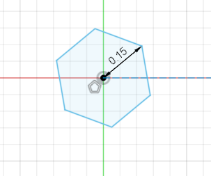
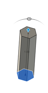
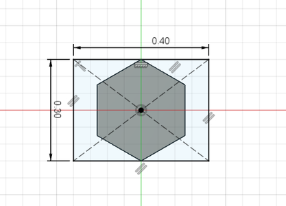
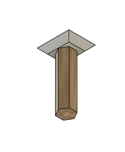
How-to: Create a new drawing and sketch a hexagon with a radius of 0.15 m and extrude by 1 m. Select the hexagonal face as a sketch plane and create a 0.3 m x 0.4 m center rectangle. Extrude by 0.1 m and with a taper angle of 45 deg.
Change the appearance of the post to cedar and the information section to aluminum.
Drag the pedestal as a component into the bridge drawing. Along the larger portion of the bridge, use the joint tool to lay one pedestal 0.9 m away from the center of each arc.
Construction:
- Pedestal Construction: Fabricate or construct the pedestals based on the chosen design and materials. If using precast components, ensure they are assembled and reinforced correctly.
- Information Display Panels: Install information display panels on the pedestals. These may be made of weather-resistant materials such as metal, acrylic, or laminated glass to protect the information from the elements.
- Mounting and Securing: Securely mount the information display panels to the pedestals to prevent vandalism or theft. Use tamper-resistant hardware if necessary.
Step 49: Tunnel: (1) Glass Mosaic

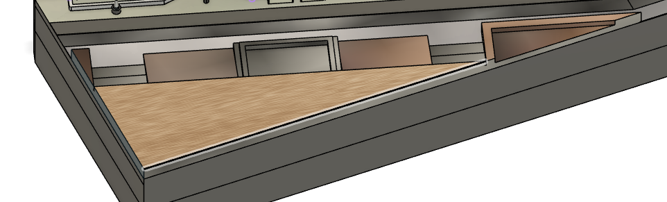
Purpose: One concept about the bridge that I was very conflicted about was roof or no roof? The primary reason for having roofs on pedestrian bridges is to protect pedestrians from inclement weather. Rain, snow, and harsh sunlight can make walking on an open bridge uncomfortable and potentially hazardous. However, an open design ensures that the bridge harmonizes with its surroundings, preserving the natural beauty of the area and avoiding visual obstructions for passersby. This allows pedestrians to better enjoy the elevated view and connect with nature on a deeper level. So, I decided, why not have both? A section on the bridge that is covered where pedestrians can seek shelter from bad weather, but also an unroofed central area that emphasizes human interaction and environmental connection.
The covered section is going to be the mosaic tunnel. A couple years ago, I heard about The Gathering of the Clans Community Mosaic Project in Todmorden Mills. The mosaic was a collective work between multiple native artists, where each piece was hand cut to produce small drawings of animals to represent various native clans. I found this really eye opening; often, we hear about asserting that the indigenous should have their own piece in the "Canadian mosaic", however, we overlook that under the umbrella of the indigenous, there is a whole other mosaic of its own, full of different, rich, and unique nations.
I decided that the idea of a mosaic was a very powerful concept when it comes to inclusivity in Canadian society, so I decided to include it in the entrance of the bridge.
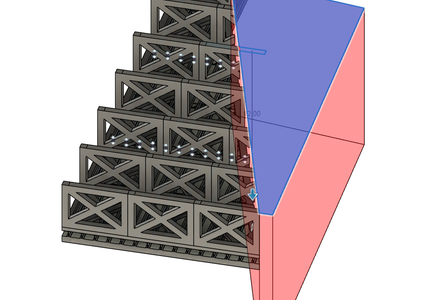
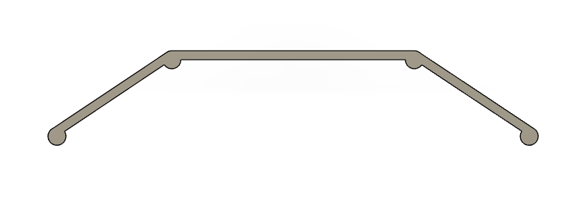
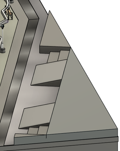
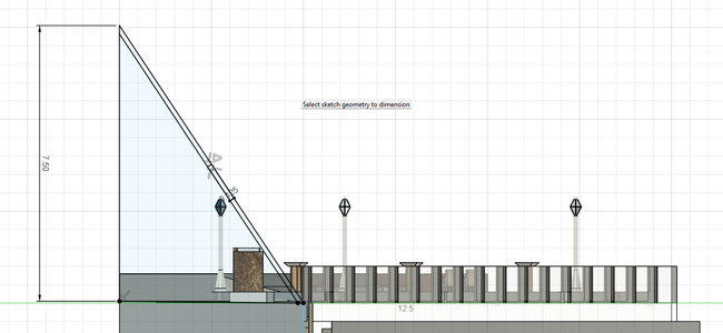
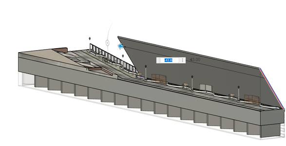
How-to: Select the very front of the bridge as a sketch plane. Along the edge, create a right-angle triangle with a base of 5 m and a height of 7.5 m. Add, a 0.125 m outline along the inside of the hypotenuse and extrude the outlined section by 43 m.
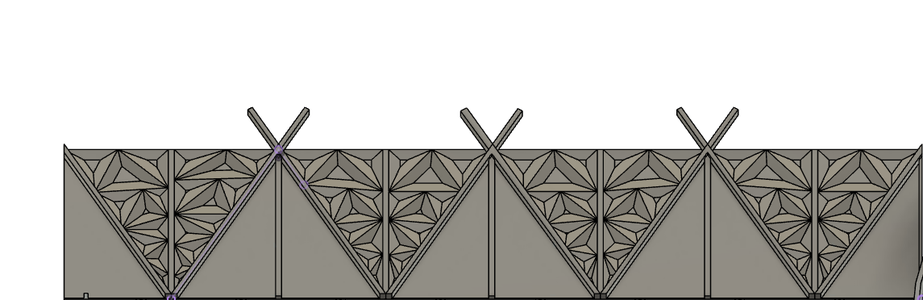
Select the outer portion of the tunnel as a sketch plane and sketch an inverted isosceles triangle through the height of the tunnel with a base of 7.5 m. Create a 0.3 m thick section through the center of the triangle.
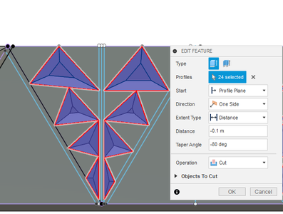
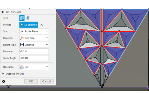
Now for the fun part! Use the line tool to fill one side of the triangle with smaller triangles, then mirror them along the center line.
When extruding the smaller triangles, *select as many as you can without having two triangles with touching sides. Extrude by -0.1 m with a taper angle of -80 deg, ensuring the operation is on cut. Repeat this for the remaining triangles in a second extrusion.
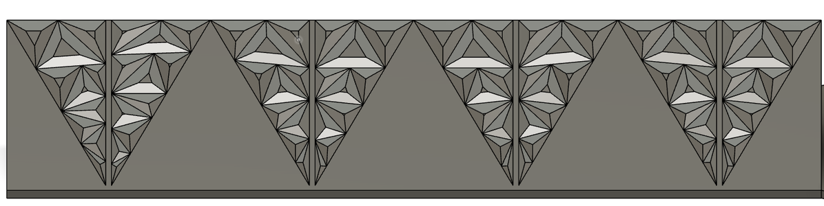
Then, repeat this entire step three more times along the remainder of the tunnel.
*The reason we need two separate extrusion is so the shape of each individual triangle can be distinguished.
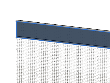
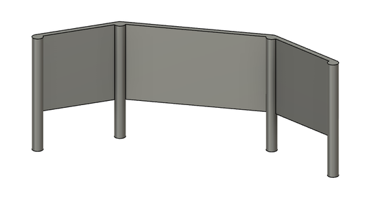
Step 50: Tunnel: (2) Warren Truss With Verticals

Purpose: For the tunnel, I needed a simple structure that could support the mosaic tunnel. The simple geometry of the Warren truss makes it relatively straightforward to design and fabricate. This simplicity reduces construction time and costs compared to more complex truss designs. The triangular arrangement of members in the Warren truss ensures stability and distributes forces evenly throughout the structure.
However, I saw a creative opportunity with the warren truss. If I slightly extended the truss members that intersected at the top of the tunnel, they would create a tipi shape. I thought this would be a powerful symbol to include in my design because tipis were designed to withstand harsh weather conditions, such as strong winds and heavy rain. The ingenuity and adaptability of the teepee design reflect the resourcefulness of Indigenous peoples and their ability to thrive in their environments. The conical shape of the teepee is often seen as symbolic of the connection between the earth and the sky, reflecting the importance of nature and spirituality in Indigenous cultures. Moreover, tipis have been used for centuries as a central part of their nomadic lifestyle, providing shelter and a sense of home while allowing for mobility across the plains.
How-to: Outline each inverted triangle with a 0.3 m thick outline. Add 0.3 m thick vertical lines going through each triangular section. This will make of the truss members to support the tunnel.
Before I extruded the supports by 0.5 m, I decided to extend the truss members that intersected at the top of the tunnel by 0.3 m.
Step 51: Tunnel: (3) Applying Apperances to the Tunnel
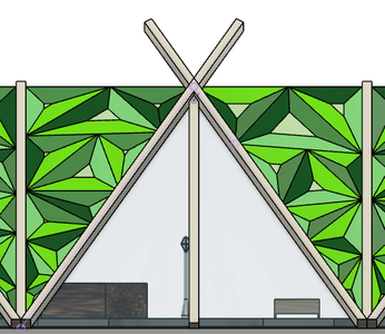
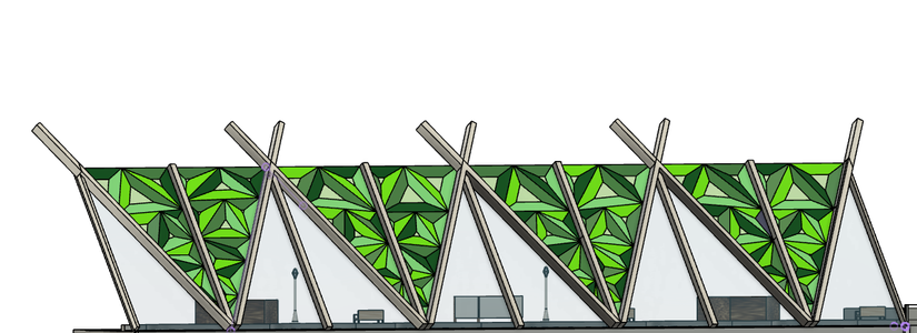
Purpose: I decided to have a green theme for the tunnel entrance. Many Indigenous cultures have a strong bond with the natural world, and green represents the abundance of plant life, forests, and vegetation that sustain their communities. Green is a symbol of the Earth's vitality and the cycle of life and growth.
How-to: Change the truss members to aluminum - cast with a rough white paint coat on top. The mosaic glass portion provides much more creative freedom. Have fun with this part and play around with different glass colours and paints!
Consutrction:
- Truss Design and Fabrication: Design the Warren truss structure to complement the glass tunnel's shape and dimensions. Fabricate the truss components, typically made of steel or other suitable materials, according to the design specifications.
- Glass Panel Production: Manufacture the glass panels in the required sizes and shapes. The panels may need to be tempered or laminated for safety and strength.
- Foundation and Footing: Prepare the bridge surface to accommodate the glass tunnel's foundation and footing. Ensure that the foundation can support the weight of the glass structure and the pedestrian or traffic loads.
- Assembly and Installation: Assemble the Warren truss components and install them on the bridge according to the design plan. Place the glass panels into the truss structure, securing them safely and with weatherproofing measures.
- Apply sealants and weatherproofing materials to protect the glass panels and truss connections from water infiltration, condensation, and environmental exposure.
Step 52: Adding Aluminum Plates to the Sides
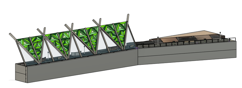
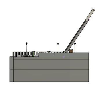
Purpose: To add a cleaner look to the bridge and create a flush surface for aesthetic additions, I decided to add thin aluminum plates to each side of the bridge, except the sides I would be using as mirror planes later. These plates would be connected to the truss through sliding bolts.
How-to: For each side, select it as a sketch plane, outline it, and extrude it by 0.5 m.
Construction:
- Cutting and Fabrication: Cut the aluminum plates to the required dimensions and shape based on the bridge's design. Fabricate any necessary holes, cutouts, or bends to accommodate specific features or requirements.
- Installation: Begin the installation by positioning the aluminum plates at the designated locations on the sides of the bridge. Ensure they are aligned correctly and fit snugly against the bridge surface.
Step 53: The Three Sisters
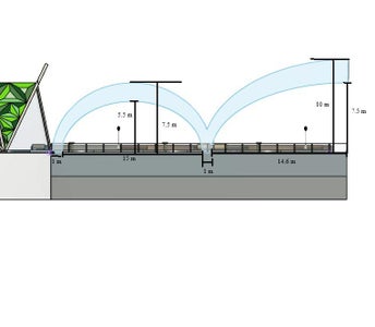
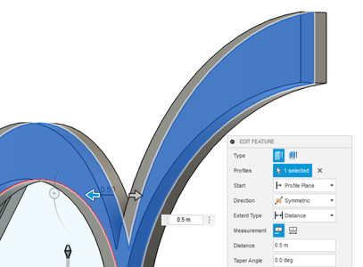

Purpose: When I was in seventh grade, my social teacher taught us about the agricultural techniques and habits of the indigenous. I do not know if it is because of the unique name or because I love my mom's famous rajma beans, I have never forgotten the concept of The Three Sisters.
In Native American cultures, the Three Sisters refer to three important agricultural crops that were traditionally grown together: corn (maize), beans, and squash. The Three Sisters crops had a symbiotic relationship when planted together; the intercropping method maximized the efficiency and productivity of the land. Corn symbolizes life, fertility, and sustenance. Beans symbolize support, unity, and strength. Squash symbolizes protection, health, and abundance.
I wanted to add this concept as a symbol in the bridge through the use of three arches, which are symbols of cooperation, interdependence and balance. At the same time, I would be paying ode to the Three Sisters Mountains in Canmore, an important landmark in Alberta.
How-to: On the wider section of the bridge, select the side of the aluminum plate as a sketch plane. 1 m away from the edge, create a 15 m wide arc with a height of 5.5 m. Create another arc around it, 1 m away from the endpoints and a center point that is 2 m higher than the original.
Next to this create an arc with a width of 30 m and a height of 7.5 m. Create another arc around this one, 1 m away from the endpoints and a center point that is 2.5 m higher than the original. Then, cut the arc in half and trim away the excess.
Select the final shape and do a symmetrical extrusion by 0.5. Chamfer each by 0.4 m and change the appearance to aluminum, followed by gold paint.
Construction:
- Fabrication and Prefabrication: Fabricate the aluminum arches off-site to the specified dimensions and design. Prefabrication allows for better quality control and quicker installation on-site.
- Lifting and Positioning: Use cranes or other lifting equipment to carefully lift and position the aluminum arches in their designated locations on the bridge.
- Installation Method: The archs will be attached to the aluminum plates through a large mount. However, welding could also be an option since it is aluminum on aluminum, meaning there is no concern about different rates of thermal expansion.
Step 54: Geometric Pattern
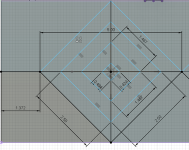
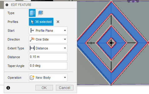
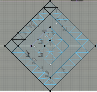
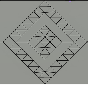
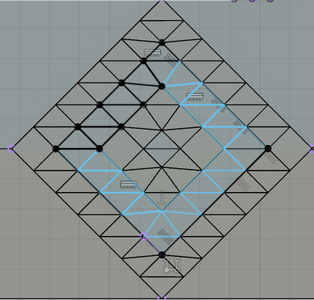
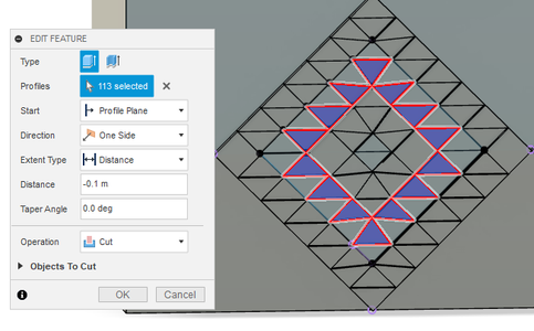
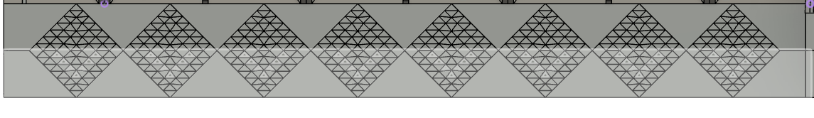
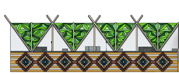
Purpose: Another one of the concepts in my bridge that I wanted to honour was native art. I decided that along the side of the walkway, there is going to be a three-dimensional native geometric pattern. Geometric patterns are an essential part of Native cultural identity, representing a visual language that reflects the heritage, history, and traditions of Indigenous peoples. They reflect the belief that all things in the universe are interconnected and in balance. The precise repetition and arrangement of shapes in these patterns express the concept of equilibrium and the interdependence of all elements in the world.
Most importantly, I wanted to showcase the richness of native culture through these patterns; The intricate, precise, and often vibrant designs are a powerful representation of the skill, creativity, and craftsmanship of Indigenous artisans.
How-to: Select the side of the walkway as a sketch plane and create a 3.5 m x 3.5 m square about 1.4 m away from the edge. Create a 2.5 m x 2.5 center square inside, followed by a 1.5 m x 1.5 m square, and finally followed by a 0.43 m x 0.43 m square. Select the outermost border and the third border from the outside and extrude by 0.15 m.
Sketch a triangular pattern within this border through a series of horizontal and perpendicular lines. Then extrude the pattern by -0.1 m, ensuring the operation is on cut. Repeat everything 7 more times to extend the pattern through the entire walkway.
Then, select the walkway as a sketch plane and sketch 9 horizontal lines 0.5 m apart. Extrude every other section by 0.1 m; I also decided to extrude the center two sections together.
Sketch a 0.14 m thick border around each geometric square, then extrude by 0.1 m.
The material should be aluminum but have some fun with the appearances! Use different paints to add some colour to the pattern, but remember to keep symmetry in mind!
Construction:
- Installation (Tiles or Panels): For tiles or metal panels, begin the installation by securing the elements to the bridge's sides using appropriate adhesives, screws, or brackets. Follow the markings to ensure the pattern's alignment and symmetry.
- Installation (Paint or Stencils): If using paint or stencils, carefully apply the paint to create the geometric pattern. Use masking tape or stencils to achieve clean and precise edges.
- Finishing and Sealing: After completing the pattern, inspect the design for any imperfections or touch-ups. Apply a weather-resistant sealant or protective coating to protect the pattern from the elements and enhance its longevity.
Step 55: Animal Design
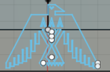


Purpose: Native cultures emphasize the importance of living in harmony with nature and recognizing humans' role as caretakers of the Earth. Animals are seen as fellow inhabitants of the land, deserving respect and protection. They symbolize various aspects such as strength, wisdom, courage, patience, or adaptability, and are revered as sources of inspiration and guidance.
Native culture has a powerful relationship to nature, and I wanted to represent that connection through an animal design on the bridge. I chose the bird because they are often associated with healing practices and divination in Native cultures. Their feathers, songs, or movements may be used in healing ceremonies, energy cleansing, or spiritual rituals.
How-to: Select the side of the wider portion of the bridge as a sketch plane. This step also allows for more creative freedom! Search online for indigenous art to get inspiration and sketch a bird design.
Start the first sketch 5.8 m away from the edge and simply use the line tool to sketch the design. My design covered a about a 5.5 m x 4 m area. Repeat the sketch twice more every 3 m. Then, extrude the designs by 0.05 m.
The materials should still be aluminum but choose any paints!
Construction:
See construction in step 50.
Step 56: Mirror


How-to: Time to do the first mirror of the bridge section!
Before mirroring, convert all of your bodies to components. Mirroring by faces is another option, but it may cause Fusion 360 to crash because there are almost 8000 faces in the project. Mirroring components is a lot faster and more easily done by the program.
After converting all the bodies to components, use the mirror tool to select everything and make the mirror plane the side of the bridge.
Step 57: Foutain


Purpose: As mentioned earlier, the purpose of the water fountain was to acknowledge the indigenous connection to water and replenishable sources. When designing the fountain, I wanted to create something more unique and preserve the geometric theme I had created with the outer patterns. With the help of some online inspiration, I decided on a skeletal pyramid shape, it was something different and eye catching, but also stayed true to the concept of geometry in native culture.
How-to: Now that the first mirror is complete, the fountain can be created!
Start a new drawing and create an isosceles triangle with a base of 3 m and a height of 5.3 m. Then, extrude the shape by 3.5 m at a taper angle of -18 deg.
Select triangular face that has a base of 3m and a height of 5.3 m and shell it by 0.1 m.
For the two larger sides, outline line them with a 0.1 m thick border and extrude by snapping to the other side of the face.
Select one open side as a sketch plane. Use the spline tool to sketch shallow arcs at 0.5 m intervals, these do not need to be perfectly shaped as they are the streams of water. Extrude by -0.02 m as a new body and repeat on the other two open sides.
Change the appearance of the skeleton to white marble and change the streams to water.
Use the joint tool to attach the base of the fountain to the reservoir. Then, select the base of the reservoir and extrude by 0.2 m as a new body. Apply a water appearance to this new body.
Construction:
Most of the features of the fountain were outlined when building the reservoirs, all that needs to happen now is the installation of the fountain itself.
Step 58: Archs


Purpose: Below the truss deck, there are going to be arches that the piers can later be joined to. Arches are excellent at transferring the weight and loads they bear down to their supports, which are usually the piers or abutments. By placing the piers below the arches, the arch can effectively transfer the load to the ground or the structure beneath it. This load distribution mechanism helps in maintaining the stability and structural integrity of the bridge. The arch shape predominantly carries compressive forces. When a load is applied to the arch, it tries to flatten out, exerting compressive forces along its curve.
How-to: Select the bottom of the bridge as a sketch plane and outline the shape, then extrude it by 1 m.
Select the walkway side of this new body as a sketch. Starting 4 m away from the edge, create 5 arches that have a width of 10 m and a height of 2 m at 4 m intervals. Do a symmetrical extrusion by 21 m. Then, create another sketch enclosing the excess material and extrude it by -5 m with the cut operation.
Change the appearance to aluminum and apply a gold paint.
Construction:
- Formwork Preparation: Formwork is built to mold the shape of the concrete arch during construction. The formwork is typically made of wood, steel, or precast concrete and must be strong enough to withstand the pressure of the wet concrete.
- Reinforcement: Steel reinforcement bars (rebars) are placed inside the formwork to add tensile strength to the concrete arch. The rebars are arranged according to the bridge's design specifications.
- Concrete Pouring: Once the formwork and reinforcement are in place, concrete is poured into the mold. The concrete mix must be of the appropriate strength and consistency. Workers may use a crane or pump to pour the concrete into hard-to-reach areas.
- Curing and Setting: After pouring, the concrete is left to cure and set. Curing is a critical process that involves keeping the concrete moist and at the right temperature to ensure proper hydration and strength development.
- Formwork Removal: Once the concrete has achieved sufficient strength, the formwork can be removed. This process must be done carefully to avoid damaging the newly formed arch.
- Post-Tensioning: In some cases, post-tensioning is used to add additional strength and flexibility to the concrete arch. Post-tensioning involves installing high-strength steel cables inside the arch and applying tension to them after the concrete has hardened.
Step 59: Bearings


Purpose: Between the piers and the bridge deck, there are going to be bridge bearings. Bridges are subject to various forces and movements, such as thermal expansion and contraction, traffic-induced vibrations, and settlement of the foundation. They allow controlled movement and flexibility, accommodating these dynamic forces and preventing excessive stress on the bridge elements.
How-to: Select the bottom face of the section between the arches as a sketch plane. Create a 2 m x 2 m square from the edge of the walkway and extrude by 0.05 m. Select the square face as a sketch plane and extrude a 0.1 m long cylinder with a 2 m diameter. Select the circular face as a sketch plane and create another 2 m x 2 m square and extrude by 0.05 m. Change the appearance of the two plates to aluminum and the center disk to rubber. This is one bearing, lay another one on the same section but 4 m away. Repeat this for the next two sections.
The fourth section is slightly larger, so lay 4 bearings every 2 m, then every 4 m, in a continuous pattern. The four section is the largest, so lay 6 bearings every 4 m then 2 m, in a continuous pattern.
Construction:
- Installation of Bearings: The selected bearings are carefully placed on the bearing seats or supports on the bridge's abutments or piers. Proper alignment is crucial to ensure the bearings function as intended.
- Bearing Fixing and Connection: Once the bearings are positioned correctly, they are fixed or connected to the bridge structure. The method of fixing depends on the type of bearing being used. For example, elastomeric bearings may be bolted in place, while pot bearings may be grouted to the bridge structure.
Step 60: Piers


Purpose: Piers are needed because they bear the weight of the bridge and transfer the loads, including the weight of the bridge itself, traffic loads, and environmental forces, to the ground or the foundation. Without piers, the bridge's weight and the loads it carries would not have a stable foundation, leading to a collapse. Moreover, this bridge is built to help cross a body of water; Piers provide the necessary support to keep the bridge deck elevated at the desired height and allow it to cross the gap safely. They prevent the bridge deck from sagging or deflecting excessively under gravity and live loads, ensuring that the bridge remains level and safe for use.
How-to: Center a 3 m x 9 m rectangle over two bearings and extrude by 1 m. On the front side, create two arc shapes that go 3 m across and 1.8 m down. Then, extrude by 3 m and chamfer edges by 0.5 m.
On the bottom face, center a 2 m x 2 m square and extrude by 5 m at a taper angle of 1.6 deg. Chamfer the edges by 0.4 m. Change the appearance to concrete with a white rough powder coat.
Repeat for every pair of bearings.
Construction:
- Formwork installation: Formwork, typically made of wood or metal, is set up inside the excavated holes to give shape to the concrete piers. The formwork ensures that the concrete is poured in the desired dimensions and shape.
- Reinforcement placement: Steel reinforcement bars, also known as rebar, are placed within the formwork. These rebar rods provide additional strength to the concrete piers by reinforcing them and helping them withstand tension and compression forces.
- Concrete pouring: Once the formwork and rebar are in place, the concrete is poured into the excavated area. The concrete mix used is specifically designed for the required strength and durability. The concrete is allowed to settle and cure properly to gain its full strength.
- Curing: Curing is a critical process that involves keeping the concrete moist and at the right temperature to allow it to set and gain strength. Curing typically takes several days to a few weeks, depending on the concrete mix and environmental conditions.
- Pier cap installation: After the piers have cured and gained sufficient strength, a horizontal platform called the pier cap is constructed on top of the piers. The pier cap acts as the base for the bridge superstructure.
Step 61: Foundation Blocks


Purpose: Bridges need foundation blocks to anchor the structure securely to the ground and distribute the loads from the bridge safely. These blocks are designed to spread these loads over a broader area, reducing the pressure on the ground and preventing excessive settlement or sinking of the bridge. Moreover, since this bridge travels across a body of water, the foundation blocks will help it withstand the forces of water flow and protect against erosion, ensuring the long-term stability of the bridge.
How-to: Select the bottom of a pier as a sketch plane. For each single pier, sketch a 5 m x 3 m rectangle. For 2 piers, create a 15 m x 3 m rectangle and for 3 piers, create a 25 m x 3 m rectangle. Extrude by 1 m.
Construction:
- Excavation: Once the layout is established, excavation work begins. This involves digging deep holes or trenches at specific points to create the foundation for the bridge piers or abutments. The depth of the excavation depends on factors like the soil condition and the load the bridge needs to support.
- Sub-Base and Footings: The bottom of the excavated holes is often filled with a layer of compacted material known as the sub-base. On top of the sub-base, concrete footings are poured to create a stable and level surface for the foundation blocks.
- Foundation Blocks: The foundation blocks, also known as bridge piers or abutments, are usually large, reinforced concrete structures that support the weight of the bridge and transfer it to the ground. These blocks are carefully positioned on top of the footings and aligned precisely according to the bridge's design.
- Reinforcement: Steel reinforcement bars are often placed within the foundation blocks to provide additional strength and prevent cracking or failure under load.
- Concrete Pouring: Once the foundation blocks are in position and any necessary reinforcement is in place, concrete is poured into the forms to create the solid structure of the blocks. The concrete is left to cure and gain strength over time.
- Curing and Inspection: After the concrete has set, it undergoes a curing process to ensure optimal strength development. During this time, inspections are carried out to check the quality of the foundation blocks and ensure they meet safety and engineering standards.
Step 62: Cutwater


Purpose: I have lived in Calgary for almost 15 years and staying that long in one place gives you the opportunity to watch it change. One thing Calgary can never be certain about is the weather; in this city, weather reporters might as well be spinning a wheel of fortune when dictating that day’s rain or shine. I’m talk about the intense rain and hail, eventually leading to floods.
This bridge carries right over the Bow River, which was one of the many sites of rapid and intense flooding during the flood of 2013. Specifically, the Bow River, peaked at eight times its regular flow rate, which was around 2,400 cubic meters per second. Therefore, it is vital to consider some kind of flood protection in the bridge design. The piers and foundation blocks would help keep the bridge stable and secure during rising water levels, but I also decided to include cutwaters.
Cutwaters are designed to split the flow of water; by dividing the water flow around the piers, cutwaters help to reduce the force of the flowing water on the bridge structure. Usually, when water flows around bridge piers, it creates turbulence that can cause localized scouring and erosion. Cutwaters are strategically shaped to minimize turbulence and create a smoother flow pattern around the piers. This helps prevent erosion around the piers, minimizing the impact of water currents on the stability of the bridge.
How-to: Select the top face of the foundation block as a sketch plane. Against the front of the pier, create an isosceles triangle with a height of 0.7 m and a base of 1 m. extrude by 4.5 m and fillet the top by 0.4 m.
Change the appearance to concrete and apply a white rough powder coat. Repeat this for the front side of every pier.
Construction:
- Formwork Setup: Formwork, typically made of wood or metal, is constructed to shape the cutwater. The formwork defines the shape and size of the cutwater and keeps the concrete in place during the pouring process.
- Pouring Concrete: Once the formwork is in place, concrete is poured into the forms to create the cutwater. The concrete is allowed to cure and gain sufficient strength.
- Finishing: After the concrete has cured, any necessary finishing touches are applied to ensure the cutwater's surface is smooth and free from defects.
Step 63: Abutment


Purpose: The bridge needs outermost supports to hold the ends of the superstructure in place; this is where abutments come into play. Abutments are responsible for retaining the earth or fill materials used to create the approach ramps leading up to the bridge. They provide lateral support to these embankments, preventing soil erosion and maintaining the bridge's alignment. Abutments also play a role in waterway and flood management as they provide openings or culverts to allow water to pass through, preventing the accumulation of water on the bridge deck and avoiding potential damage.
How-to: Select the front side of the arch as a sketch plane. From the corner, create a 2 m x 4 m rectangle with a right triangle below with a base of 4 m and a height of 4 m. Extrude by 0.5 m and repeat on the opposite side. Outline the triangle and extrude it by 10 m under the bridge.
Select the side of the abutment as a sketch plane and create an 8 m x 12 m upside-down "L"- shape that is 2 m thick. In the corner of the "L", create a right-angle triangle with a base of 4 m and a height of 4 m. Extrude by 11 m and change the appearance to concrete.
Construction:
- Formwork Installation: Once the foundation is in place and cured, formwork is installed to shape the abutment structure. Formwork is typically made of wood, metal, or a combination of both and serves as a mold for the concrete that will be poured later.
- Reinforcement: Steel reinforcement bars, often referred to as rebar, are placed within the formwork to provide additional strength to the concrete abutment. The rebar is positioned according to the engineering specifications and design requirements.
- Concrete Pouring: After the formwork and rebar are in place, concrete is poured into the formwork. It is important to use high-quality concrete to ensure the longevity and stability of the abutments.
- Curing: Once the concrete is poured, it needs time to cure properly. Curing is the process of keeping the concrete moist and at the right temperature for a specific period. This allows the concrete to gain strength and durability.
Step 64: Approach Slab


Purpose: Approach slabs provide a smooth and gradual transition between the bridge and the on-land sidewalks or embankment. This helps to reduce the impact of sudden changes in elevation, minimizing discomfort for passengers. Additionally, bridge structures and highways may experience settlement or movement over time due to various factors like soil consolidation, temperature changes, or external forces; approach slabs accommodate these movements, reducing the risk of cracking or other damage at the junction between the structure and the road.
How-to: Select the top of the abutment as a sketch plane. Create a 6 m x 8 m rectangle and extrude by 0.05 m. Change the appearance to concrete-tile.
Construction:
See construction in Step 29.
Step 65: Final Mirror


How-to: Time for the final mirror, this is where the final form of the bridge is created!
First, make sure to convert all bodies to components. Then, make a selection of the entire structure and select the mirror plane as the stage side.
Step 66: The Gardens


Purpose: Intially, I believed that I would be able to add garden and trees from free online 3-D databases, however that proved to be difficult. They would often not be in .f3d format, making it challenging to import them in Fusion 360. In the end, I decided to build the garden and trees myself.
How-to: Create a new drawing. Start by extruding a 4 m long cylinder with a diameter of 0.5 m. Then, select one of the circular faces as a sketch plane and create a 3 m x 3 m sqaure, follow with a symmetrical extrusion by 1.5 m with the operation on new body.
Use the sphere tool to join multiple spheres of different radii into the cube to create a tree-like shape. Change the material of the tree to cherry wood and apply appropriate colours using paint.
Drag the tree in the bridge drawing and use the joint tool to attach it to the tree garden, repeat this for the other three gardens.
For the flower arch gardens, I created my own appearance. First, I duplicated a concrete-tile appearance and edited it. I replaced the concrete image with an image of some flowers that I found on Pexels, an open-domain image sharing source. Then, I applied the appearance to all of the gardens. I repeated this to add grass to the tree gardens.
Construction:
- Soil and Drainage: Prepare the bridge surface for gardening by ensuring proper soil quality and drainage. If necessary, add suitable soil to create a healthy growing environment for the plants.
- Plant Selection: Choose plants that are well-suited to the bridge's environment, including the amount of sunlight, wind exposure, and the ability to tolerate temperature fluctuations. Select a mix of perennials and annuals to create a dynamic and ever-changing garden.
- Planting: Carefully plant the chosen vegetation, taking care to arrange the plants according to the design plan. Consider the height, color, and texture of the plants to create an appealing visual effect.
Step 67: Render


How-to: Change your workplace to render. Go to set-up and select scene settings. The default background will be set to solid colour, change this to "environment". Then, go to the environment library panel and play around with the different backgrounds provided in the Fusion 360 library. If one does not suit your structure or its purpose, there are plenty of online websites that offer free HDR backgrounds. I used some environments from Poly Haven.
Select the tea pot in the tool bar to render. I rendered with the cloud renderer.
Step 68: Feedback From Real Engineers
When designing anything, it is important to get feedback from experts.
Shahzeb A. is a fourth-year software engineering student at the Schulich School of Engineering at the University of Calgary. I asked him to provide some insight into my bridge. He suggested that I missed some opportunities to enhance the safety of my bridge by not considering sensor technology. Sensors can continuously monitor the health of the bridge's components, such as beams, cables, and foundations. They can help detect and assess structural damage, cracks, or deformations, allowing for early detection of potential issues before they become critical. This proactive approach prevents catastrophic failures and extends the bridge's lifespan. From a software perspective, Shahzeb A. argued that sensors can be connected to a centralized system, allowing engineers to monitor the bridge's condition remotely. This capability simplifies maintenance planning and reduces the need for physical inspections, making the process more efficient and cost-effective.
This meant I had a lot of research to do in regards to bridge sensor technology.
Before I revisited my bridge, I needed a second opinion as well. I decided to ask Muhammad I., who is a mechanical engineer from the Southern Institute of Alberta (SAIT). Like with Shahzeb A., I wanted an engineering expert to look over my design to weed out any potential errors or factors I should think about including. He seemed very happy with how I chose to connect my design to the indigenous people and truth and reconciliation. However, he pointed out that there were some components in my bridge that contradicted one of the purposes of my design, which was to respect and honour native culture and values.
He argued that the more technological parts of my bridge, such as the drip irrigation system, streetlights, fountain pump, and also the sensors I would eventually add, would need energy to run. I initially stated that these systems would use electricity, but I failed to consider that Alberta is one of the many provinces in Canada that relies on coal-fired power plants. That meant that my bridge would be a contributor to the greenhouse gas (GHG) effect and climate change; this is where my bridge contradicted indigenous beliefs and way of life. Muhammad I. reminded me that many native cultures believe that people have a responsibility to be stewards of the environment, they must take care of it in a way that it is preserved for future generations. Having systems on my bridge that were fueled by a GHG emitter and a non-renewable resource was not environmental stewardship.
I had to find an innovative way to incorporate renewable resources in my bridge to run the systems that needed electricity.This would not respect indigenous values, but also help the city move towards adopting more environmentally friendly and self-sufficient infrastructure.
Step 69: Revisiting: Sensor Technology


After doing research, I found that incorporating sensor technology in a bridge can significantly enhance its structural health monitoring and improve overall safety. Sensors can provide real-time data on various parameters, enabling engineers to detect potential issues early, assess the bridge's condition, and make informed decisions about maintenance and repairs. Here's how sensor technology can be integrated into my bridge and where the different sensors should be placed:
Strain Sensors
- Description: Strain sensors, also known as strain gauges, measure the deformation or strain experienced by a bridge component. They work on the principle of electrical resistance change in response to mechanical deformation; they are essential for monitoring the structural integrity of the bridge.
- Working Principle: When subjected to strain, the resistance of the sensor changes, which can be measured to determine the strain in the bridge element.
- Types: Electrical resistance strain gauges and fiber optic strain sensors.
- Application: Monitoring stress and load distribution on critical bridge elements such as beams, piers, and trusses.
Accelerometers
- Description: Accelerometers measure the acceleration or vibrations experienced by the bridge due to dynamic forces, such as traffic loads, wind, or earthquakes. These sensors are essential for assessing the bridge's dynamic behavior and identifying potential resonance issues.
- Working Principle: They detect the acceleration using various technologies like piezoelectric, MEMS (Micro-Electro-Mechanical Systems), or capacitive sensing.
- Types: MEMS accelerometers, piezoelectric accelerometers.
- Application: Assessing the dynamic behavior, natural frequencies, and potential resonance issues of the bridge. They should be strategically placed on key sections of the bridge, including the deck and piers.
Temperature Sensors
- Description: Temperature sensors monitor the temperature variations experienced by the bridge to understand thermal expansion and contraction effects.
- Working Principle: Different technologies like thermocouples, resistance temperature detectors (RTDs), or thermistors are used to measure temperature.
- Types: Thermocouples, RTDs, thermistors.
- Application: Monitoring temperature changes in critical bridge elements to prevent thermal stress-related issues. Temperature sensors should be distributed along the bridge to monitor thermal changes and their impact on the structure.
Load Cells
- Description: Load cells are used to measure the applied load on the bridge, which is crucial for understanding the stress distribution and ensuring that the bridge operates within safe load limits.
- Working Principle: Load cells use strain gauges or other technologies to convert the applied force into an electrical signal.
- Types: Strain gauge load cells, hydraulic load cells, piezoelectric load cells.
- Application: Monitoring live loads, traffic loads, and assessing the load-carrying capacity of the bridge. Load cells can be placed at various points, such as the bridge's supports or under specific segments.
Displacement Sensors
- Description: Displacement sensors measure the relative movement between different parts of the bridge.
- Working Principle: They can use various technologies, such as potentiometers, laser displacement sensors, or linear variable differential transformers (LVDTs).
- Types: LVDTs, potentiometers, laser displacement sensors.
- Application: Monitoring joint movements, expansion and contraction, and detecting excessive displacements. They can be placed in critical joints and expansion points to monitor any excessive movement, which may indicate wear or damage.
Corrosion Sensors
- Description: Corrosion sensors detect the degradation of steel elements caused by environmental factors, particularly in corrosive environments.
- Working Principle: Various techniques, such as electrical resistance or electrochemical methods, are used to measure the rate of corrosion.
- Types: Electrical resistance corrosion sensors, electrochemical corrosion sensors.
- Application: Monitoring the corrosion rate of steel elements and assessing the health of the bridge in corrosive environments. These sensors should be placed near vulnerable areas where corrosion is more likely to occur, such as on piers and foundation blocks.
Crack Detection Sensors
- Description: Crack detection sensors are embedded in concrete elements to detect the formation and propagation of cracks.
- Working Principle: They may use fiber optic technology or electrical resistance methods to detect cracks.
- Types: Fiber optic crack sensors, electrical resistance crack sensors.
- Application: Monitoring the development and growth of cracks in concrete structures. In this project, crack detection sensors can be embedded into vital concrete portions of the bridge, such as the arches, piers, and foundation blocks.
Water Level Sensors
- Description: Water level sensors can monitor flood conditions and assess potential risks during heavy rainfall or flooding events. These sensors are especially important for my bridge since it crosses the Bow River, which has experienced rising water levels and flooding in the past due to intense rain.
- Working Principle: Different technologies like ultrasonic or pressure-based methods are used to measure water levels.
- Types: Ultrasonic water level sensors, pressure transducer water level sensors.
- Application: Assessing flood conditions and potential risks during heavy rainfall or flooding events. These sensors should be placed on the foundation blocks and piers.
Wind Sensors
- Description: Wind sensors measure wind speed and direction to assess the impact of wind loads on the bridge structure.
- Working Principle: Anemometers or ultrasonic technology is commonly used to measure wind speed, and wind vanes are used for direction.
- Types: Cup anemometers, sonic anemometers, wind vanes.
- Application: Understanding the effect of wind loads on the bridge's stability and aerodynamic behavior. Wind sensors can measure wind speed and direction to assess the impact of wind loads on the bridge structure. They should be installed at various heights to capture wind behavior at different elevations.
Humidity and Environmental Sensors
- Description: These sensors monitor humidity, air quality, and other environmental factors that may affect the bridge's materials and condition.
- Working Principle: Different sensors are used to measure humidity, air pollutants, and other environmental parameters.
- Types: Humidity sensors, gas sensors, particulate matter sensors.
- Application: Assessing the impact of environmental conditions on the bridge's structural health and durability.
I found that the choice of sensors depends on the specific requirements of the bridge, its design, and the potential risks it may face. Properly selected and strategically placed sensors can provide valuable data for efficient bridge maintenance and management.
Step 70: Revisiting: Exploring Energy Sources


Addressing the energy source problem was a very important one not only towards the design and efficiency of the project, but the very purpose of it. Muhammad I. was right, having systems on my bridge that were running on coal-fired power plants undermined native values of preserving the environment, even if almost 90% of electricity in Alberta comes from fossil fuels.
I first explored the more obvious natural resources, the ones that we are more familiar with: wind, solar and hydroelectric power.
Wind: The first resource I decided to rule out was wind power. Initially, I thought this idea might show promise because Alberta has seen an in increase in wind-supplied net-to-net generation. Of the total installed generation capacity, 20 percent represented wind power with an additional 10 wind facilities in 2022. However, wind is not reliable in Alberta; it is intermittent and variable, depending on weather conditions. Bridges in certain locations may not experience consistent or strong winds, making wind power generation less reliable compared to other regions more suitable for wind farms. Moreover, incorporating wind turbines may introduce additional stresses on the bridge's structural components. Proper engineering and safety measures must be implemented to ensure the bridge's integrity and longevity and prevent potential risks to the public.
Solar: Then, I decided to look into integrating solar power into the bridge. Solar power generates electricity without producing harmful greenhouse gas emissions, air pollutants, or toxic byproducts. It relies on the sun, which is an infinite and renewable energy source, ensuring sustainability for future generations. If installed on the bridge, the solar panels would have low operating and maintenance costs. The energy production is relatively predictable, and maintenance requirements are minimal, resulting in long-term cost savings. However, there is a question that remains: where? The bridge will have limited surface area available for solar panel installation and the available space may not be sufficient to generate a significant amount of electricity to make the installation economically viable.
I looked into the Solar Wind Bridge, a bridge design that won second prize in the Solar Parks Works - Solar Highway Competition. This design incorporated "solar roadways" where a grid of solar cells coated with a transparent plastic coating replaced the usual asphalt road surface. Although this provided an efficient area for the installment of the panels, there would be lots of technical and practical challenges associated with incorporated solar panels in a bridge design.
- The cost of manufacturing and installing solar panels on a large scale to cover entire road networks would be astronomically high compared to conventional road construction.
- Solar panels are not designed to withstand such heavy loads and abrasion, but roads are often subjected to constant wear and tear from traffic, temperature fluctuations, and other environmental factors. While coating them in a durable plastic may offer some protection, it is unclear how well they would hold up over time, and the maintenance and replacement costs could be significant.
- Solar panels on roads could impact safety; the smooth surface of the panels may reduce tire traction, especially in wet conditions, potentially leading to accidents between pedestrians and cyclists.
Hydroelectric: Hydroelectric power works by harnessing the kinetic energy of flowing or falling water to turn turbines. These turbines are connected to generators, converting the mechanical energy into electricity, providing a renewable and clean source of power. If installed into the bridge, the turbines would have to be placed at regular intervals along the foundation blocks underwater. However, it is important to consider that installing turbines in rivers can affect the natural flow and ecosystems. And, more importantly, given the location, installing hydroelectric turbines would not be efficient. A strong water flow is needed to enhance the efficiency and electricity generation capacity of turbines. However, the Bow River is not a relatively deep body of water and the water flow for the section that runs along Baker Park and Bowness Park is much calmer since the river is slightly shallower.
Step 71: Vibrant Pack Energy Harvesters


It seemed that all the more common renewable energy sources would not be compatible with my bridge design. I set out to do more research and came across "Vibrant Pack Energy Harvesters".
These devices do not need to be wired to a power source, have a cheap manufacturing cost, and are relatively small, around 5-10 cm in length. This device is made up of a tube that contains a small ball and as this device absorbs low frequency vibrations, the ball rolls forwards and backwards. As it moves, the ball impacts dielectric membranes which generate an electric charge when stretched and returned to its undeformed state. This energy can be harvested and stored in a battery.
I found that this energy source was not only environmentally friendly, but also resourceful and innovative. My bridge is largely made up of steel and concrete, which are both capable of carrying lower frequency vibrations from traffic and wind. A large problem associated with bridges is how repeated vibrations from wind and traffic, especially at resonant frequencies, can lead to fatigue and wear on the bridge's structural components over time. Fatigue cracks may develop in critical areas, compromising the bridge's overall stability and safety. When external forces, such as traffic loads or winds, match the natural resonant frequency of the bridge, vibrations can be amplified. This phenomenon, known as resonance, can significantly increase the amplitude of vibrations, potentially causing structural damage.
The piezoelectric devices harvest the potentially detrimental low frequency vibrations and repurpose them into electricity for the power-requiring systems on the bridge. This energy source was perfect; because of its smaller size, the device could be placed at large scales at almost anywhere on the bridge. However, it would be strategic to place these devices on the piers, trusses, and I-beams, since these are the parts of the bridge that are most likely to encounter vibrations from live loads and winds.
Step 72: What I Learned
This was the first big project I completed on Fusion 360. Intially, I saw this a project as an opporutnity that could help fuel my education and design skills as I will be entering the University of Calgary for civil engineering in the Fall. However, I found that creating a bridge design in Fusion 360 for the scholarship contest has been an exhilarating and eye-opening experience! Throughout this project, I've not only deepened my knowledge of engineering and design principles but also gained valuable insights into the real-world application of my skills.
- The Power of CAD: One of my most significant takeaways from this endeavor is the power of technology and how it can empower us to bring our wildest imaginations to life. If you were to tell me 3 months ago that I was going to design The Legacy Passage, I would not have believed you! Fusion 360 has been an absolute game-changer in the design process.
- Proactivity and a Desire to get Better: Moreover, this project has reinforced my understanding of the importance of collaboration and seeking feedback. As I delved into the intricacies of my bridge design, I realized that engaging with fellow students and professionals in the field significantly enriched my understanding. The exchange of ideas and perspectives sparked a continuous cycle of improvement, helping me make my design more robust and innovative.
- Responsibility: Creating a bridge design has also instilled a strong sense of responsibility in me; it has been incredibly motivating knowing that my design could potentially have a positive impact on society by improving transportation and connectivity. I've learned that as a designer, it is essential to be mindful of the safety, durability, and environmental impact of the structures we create. I forced myself to dive deeper into the construction of bridge where I was able to learn about:
- Bridge Types: During the initial stages of the project, I delved into the various types of bridges, such as truss, arch, beam, and suspension bridges, where each type presented its unique design considerations and structural properties. (This understanding was vital in selecting the most suitable bridge type for the specific project requirements.)
- Balancing Aesthetics and Functionality: I realized that bridge design goes beyond mere functionality; it is also an opportunity to create an aesthetically pleasing structure that complements the surrounding environment. I had a lot of difficulty rendering as I often could not find a suitable HDR background and the environments in the Fusion 360 library were not suitable for a birdge render. However, in the end, Fusion 360's visualization tools helped me to balance both functional requirements and visual appeal, resulting in a bridge that harmonizes with its surroundings.
- Compliance with Regulations: I found that being an engineer is not all fun and games, there are rules! As part of the design process, there were many things I had to consider such as:
- local building codes
- safety standards
- environmental regulations
- When I was designing, I would often have fusion 360 on one half of the screen and a bunch of instruction manuals on the other side. It was a very tedious and painstaking process! But, by the end, I had a whole new respect for engineers as I learned how important it is to stay up-to-date with the latest standards to incorporate them into a design.
- Renewable Energy Integration: This was somethign that Muhammad I. pointed out for me when providing me with feedback. Integrating piezoelectric devices was a sustainable choice that reduced the bridge's reliance on conventional energy sources, while also, at the same time contributing to the community's overall energy efficiency.
- Going Beyond Technicalities: Participating in this contest allowed me to recognize that our community is more than just a physical location; it is a network of individuals with shared experiences and aspirations. Every decision I made was done purposefully to create something that would not only connect the physical spaces themselves but also bring people closer together in both a social and emotional way.
- The Truth behind Calgary: While I was doing my research into the history of Baker Park and Bowness Park, I underwent a deeply emotional and eye-opening experience as I learned about my city's atrocious history with the First Nation people of the land. I have lived in Calgary for as long as I can remember so it was difficult to comprehend its dark history. For me, Calgary is home and I have known it as a reputable city that always puts the interests and values of the people living there above everything else. It made me contemplate the ethical responsibility we have as professionals to recognize the impact our work can have on communities and how we can design infrastructure in a way that heals and nurtures relationships between people. Now, more than ever, I feel a strong duty to be an active part of the reconciliation process; to listen, learn, and advocate for change in any way I can. And, right now, that way is through engineering.
Step 73: Questions and Feedback

Please feel free to ask me any questions about the materials, structural elements, or the inspiration behind the aesthetics in the comments below. Your inquiries will help me refine my project and learn from your valuable insights.
Moreover, if you see any areas with room for improvement or anything that does not look right from an engineering standpoint, please let me know! Your feedback is incredibly valuable to me as I continue to grow as an engineer and a designer. Please take a look and let me know what you think! Any suggestions or critiques will be greatly appreciated!
Step 74: Phew! Thank You and That's All!


I started this project back in May, so it has been around 3 months! It was definitely difficult in the beginning with having to juggle my project with school and extracurriculars. June ended in a frenzy with my final exams, however I'll admit, I was more invested in the bridge; out of the mountain heap of papers in my room, I will shamelessly say all of them were part of my bridge design except a handful of Calculus problems.
A lot of blood, sweat, and tears went into this project. OK. Maybe not blood.
But, when I was designing this project, a lot of hard work went into building a meaningful project that served a community purpose. It was very difficult having to read the some of the gruesome and vile acts committed against native people by government institutions and community members. I wanted each component in the design to connect to this concept and I hope that you were able to see the how each decision was purposefully and passionately made.
Engineering is something I has always had my heart and I feel so grateful that I was able to provide a solution to a historical problem using my technical skills. This was a wonderful journey and I feel I have learned so much; I am incredibly grateful to the Autodesk Team that made this contest possible. I never would have thought I would get a chance to share a project of this scale; it has made my visions for the world feel tangible and I feel inspired to generate a dozen more.
For those who are reading this, I hope you were able to take something away as well, whether that be about CAD technicalities or indigenous history.
Kind regards,
Marukh Zafar
Step 75: Sources
- https://adatile.com/why-easy-access-is-important-for-wheelchair-ramps/
- https://precast.org/2012/10/why-rebar-spacing-is-crucial/
- https://plasticinehouse.com/rebar-in-concrete-footings/
- https://www.whitecap.com/rebar-cutting-and-bending-tools/rebar-tying-variations#:~:text=Start%20with%20a%20saddle%20pattern,a%20moderate%20amount%20of%20strength.&text=The%20figure%2Deight%20tie%20is,used%20in%20earthquake%2Dprone%20areas.
- https://www.bnproducts.com/blog/should-you-be-tying-or-welding-rebar/#:~:text=Many%20people%20avoid%20welding%20rebar,where%20the%20concrete%20can%20crack.
- https://www.austenknapman.co.uk/blog/news/rebar-faq-what-is-reinforcing-steel-bar/
- https://theconstructor.org/practical-guide/steel-reinforcement-types-grades/24730/#:~:text=Steel%20reinforcement%20bars%20or%20rebars,equals%20to%20that%20of%20concrete.
- https://www.eaglerocktradingpost.com/symbol-meanings#:~:text=The%20meaning%20of%20the%20Eye,West%20of%20the%20physical%20world.
- https://www.engineersedge.com/standard_material/Steel_ibeam_properties_2.htm
- http://chrome-extension://efaidnbmnnnibpcajpcglclefindmkaj/https://www.steelconstruction.info/images/c/c7/GN_2-11.pdf
- https://support.tekla.com/doc/tekla-structural-designer/2023/ref_shearconnectorscompositebeamsaisc360#:~:text=the%20spacing%20of%20connectors%20in,given%20in%20the%20next%20item
- https://www.c-beams.com/bracing-steel-beams/
- https://www.thisoldhouse.com/stairs/21017052/how-to-build-granite-porch-stairs
- https://www.ncbi.nlm.nih.gov/pmc/articles/PMC3064866/
- https://www.ncbi.nlm.nih.gov/pmc/articles/PMC2776010/
- https://www.c-beams.com/bracing-steel-beams/
- https://www.ncdot.gov/initiatives-policies/Transportation/bridges/historic-bridges/bridge-types/Pages/truss.aspx
- https://www.structuralbasics.com/howe-truss/
- https://www.encyclopedia.com/environment/encyclopedias-almanacs-transcripts-and-maps/gardens-gardens-indigenous-traditions
- https://medium.com/@mehdimirzaie/are-traditional-arts-dying-2bb03af8b00d
- https://wagnercompanies.com/o-canada/
- https://www.thecanadianencyclopedia.ca/en/article/potlatch
- https://www.finehomebuilding.com/project-guides/framing/2-rules-comfortable-stairs
- https://www.sciencerendezvous.ca/million-tree-project/en/resources/why-trees-matter-a-first-nations-perspective/
- https://www.irrigationdirect.ca/Drip-Irrigation-Systems/#:~:text=Drip%20Irrigation%20systems%20are%20an,most%20efficient%20methods%20of%20watering.
- https://torontoobserver.ca/2015/10/30/mosaic-honours-the-history-of-local-indigenous-peoples/
- https://www.britannica.com/technology/Warren-truss-bridge
- https://www.nal.usda.gov/collections/stories/three-sisters#:~:text=and%20the%20Southeast.-,The%20Iroquois%20and%20the%20Cherokee%20called%20corn%2C%20bean%2C%20and%20squash,squash%20throughout%20of%20the%20field.
- https://tallgrassandthunder.info/geometry/
- https://storymaps.arcgis.com/stories/20bae302e0b2472594bc64663a8da7fc
- https://www.britannica.com/technology/arch-bridge
- https://blog.enerpac.com/bridge-bearings-and-how-they-are-maintained/
- https://theconstructor.org/structures/bridge-pier-types/36121/
- https://constrofacilitator.com/the-bridge-foundation-advantages-and-types/
- https://stonearchbridges.com/2020/04/07/two-benefits-of-cutwaters/
- https://civilengineeringbible.com/article.php?i=261
- https://www.dot.state.oh.us/Divisions/Engineering/Structures/bridge%20operations%20and%20maintenance/PreventiveMaintenanceManual/BPMM/slabs/apprslabs.htm
- https://civionicengineering.com/structural-health-monitoring/
- https://www.mistrasgroup.com/how-we-help/monitoring/bridges/
- https://qbios.gatech.edu/new-vibrant-pack-energy-harvesters-harness-big-bridge-vibrations
- https://www.extremetech.com/energy/155102-energy-harvester-that-creates-power-from-ambient-vibrations-finally-comes-to-market
- https://www.energy.gov/eere/wind/advantages-and-challenges-wind-energy
- https://www.energy.gov/eere/solar/how-does-solar-work
- https://www.energy.gov/eere/water/how-hydropower-works#:~:text=Hydropower%2C%20or%20hydroelectric%20power%2C%20is,or%20other%20body%20of%20water.
*All external images are public domain
First Prize in the
Make It Bridge


4 Comments
11 days ago
Great Job! Love the details and research.
Reply 5 days ago
Thank you, I really appreciate it!
5 days ago
Incredibly well done tutorial!
Reply 5 days ago
Thanks, I’m glad you think so!